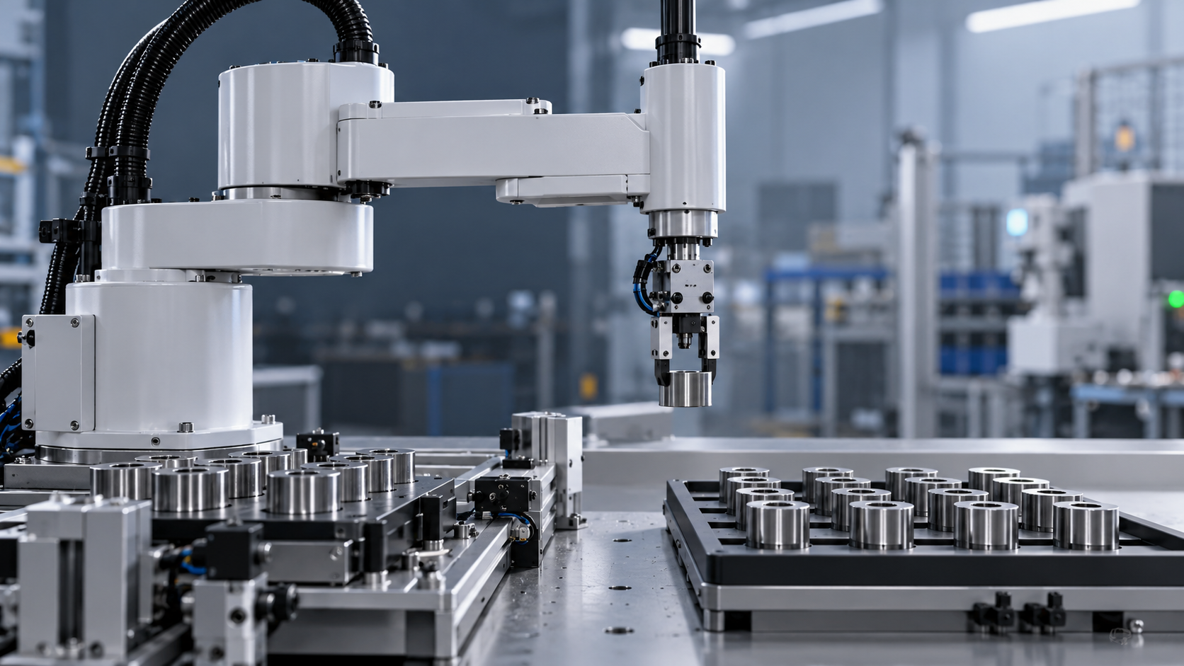
SCARA Robot Cycle Times: How Payload and Travel Distance Affect Speed
When evaluating SCARA robots, fast cycle time is only meaningful in the context of the load and motion profile used to measure it.
Payload weight, travel distance, acceleration, and settling time all influence how quickly a robot can complete a pick-and-place operation.
This article examines how payload and travel distance affect SCARA robot cycle times, helping technical evaluators compare specifications and assess throughput against real application requirements.
The practical conclusion is straightforward: a robot with the lowest published cycle time will not necessarily deliver the highest throughput in your cell.
Compare candidates using the same payload, tool inertia, travel path, accuracy requirements, and peripheral timing before treating a specification as evidence of production performance.
What Does a Published SCARA Cycle Time Actually Measure?
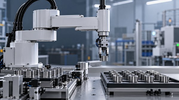
A published cycle time is the duration required to complete a defined sequence of movements under specified conditions, often expressed in seconds per cycle.
Many manufacturers use a standardized pick-and-place path, but the exact horizontal distance, vertical movement, payload, and measurement conditions must be checked for each model.
One common benchmark is a 25–300–25 mm path: 25 mm vertically, 300 mm horizontally, and 25 mm vertically at the destination.
This shorthand does not automatically describe the full production cycle. Confirm whether the stated time includes the return journey and how the manufacturer defines completion.
Also check whether the figure includes gripping, releasing, communication delays, and settling within a specified tolerance. These details determine whether two numbers are comparable.
A benchmark is useful for screening, but your application may require different distances, orientations, approach heights, or pauses that change the ranking of competing robots.
How Does Payload Weight Affect SCARA Robot Speed?
As payload increases, the robot must accelerate and decelerate more mass. Controller limits may reduce acceleration to protect motors, gearboxes, and mechanical structures.
The effect is not necessarily linear. Moving from a light load to a heavier one may have little impact until a controller limit becomes active.
Near the upper end of a robot's usable payload range, reduced acceleration and longer settling can materially increase cycle time, particularly on short moves.
Rated payload is a capacity limit, not a guarantee that the robot will maintain its best published cycle time at every permissible load.
Calculate the carried mass as the sum of the workpiece, gripper, mounting hardware, sensors, cables, and any other equipment supported by the robot flange.
For example, a 0.8 kg component held by a 1.2 kg gripper represents at least 2.0 kg of payload before accounting for mounting hardware.
A light workpiece can therefore become a demanding application when a large vacuum manifold, camera, or quick-change mechanism adds substantial mass to the tool.
Ask suppliers for cycle-time measurements at your actual total payload, rather than extrapolating from a figure measured with an empty or lightly loaded flange.
Why Tool Inertia and Center of Gravity Matter
Mass alone does not describe how difficult a tool is to move. Its center of gravity and rotational inertia can also limit robot performance.
A long gripper holding a part far from the flange generally imposes greater rotational demand than a compact tool of the same total mass.
In particular, wrist rotation can slow when the tool's moment of inertia approaches the manufacturer's allowable limit, even if total payload remains acceptable.
Check permissible inertia, center-of-gravity offsets, and payload limits together. These constraints may vary with tool orientation, acceleration, and the robot's operating configuration.
Reducing an unnecessary offset or using a lighter gripper can improve acceleration and settling without purchasing a larger robot. Verify the change against gripping requirements.
Provide the supplier with a tool drawing, mass properties, and the location of the center of gravity so its assessment reflects the actual assembly.
How Does Travel Distance Change Cycle Time?
Longer travel usually increases cycle time, but not in direct proportion to distance. The result depends on acceleration, deceleration, and achievable peak speed.
For a short move, the robot may begin slowing down before reaching maximum speed. Acceleration and settling then dominate the movement time.
For a longer move, the robot may reach a sustained speed between acceleration and deceleration. Maximum velocity becomes more influential in that portion.
A simplified symmetric motion model illustrates the difference. With distance d and acceleration magnitude a, an ideal short move takes approximately 2√(d/a).
That estimate assumes the robot starts and ends at rest, uses constant acceleration, and does not reach a velocity limit. It excludes settling and process delays.
If the move reaches a velocity limit v, the same simplified model gives approximately d/v + v/a, provided the distance is sufficient.
Real SCARA motion uses joint-dependent limits and programmed trajectory profiles, often including jerk constraints. Treat these equations as intuition, not as a vendor quotation.
Measure the complete route, including vertical clearance, horizontal transfer, wrist rotation, approach, departure, and return. Straight-line station spacing alone understates the work involved.
Obstacle clearance matters: raising the tool farther than necessary at both ends can add time, especially when the cycle repeats thousands of times per shift.
What Else Determines the Real Pick-and-Place Cycle?
Acceleration settings influence cycle time, but aggressive motion can increase vibration, cause a part to slip, or extend the time needed to settle.
Settling time is the interval required for the tool or part to stabilize sufficiently after a move. The acceptable tolerance depends on the operation.
A loose bin placement may need little settling, while insertion into a close-fitting fixture or camera inspection may require a longer, more stable dwell.
Gripper timing matters too. Vacuum generation, pressure confirmation, mechanical jaw travel, and release verification can each add delays outside the robot's motion time.
Vision processing, programmable logic controller communication, and machine readiness signals may also affect the cycle, although some tasks can run in parallel with robot movement.
For a serial sequence, add the durations of robot moves and nonoverlapping process steps. For parallel operations, model the critical path rather than adding everything.
Finally, compare consistent start and end points. A time measured from one pickup to the next pickup differs from a one-way transfer measurement.
How to Compare SCARA Robots for Your Application
Start by defining the production cycle as a sequence: acquire the part, confirm the grip, transfer, place, release, and return to the next pickup.
Record each waypoint, required orientation, vertical clearance, and acceptable placement tolerance. Include the worst credible variation in pickup and placement positions.
Specify the complete tool mass, payload mass, center of gravity, and inertia. Identify whether the robot must rotate the part while carrying it.
Next, ask each supplier to evaluate the same path and conditions, including controller settings, grip delays, settling criteria, and any simultaneous motion allowed.
Request both simulated and measured results where available. Simulation is valuable for early screening, but its accuracy depends on realistic tool and process assumptions.
A physical trial is especially useful when handling flexible parts, using high acceleration, performing precision insertion, or working close to a payload or inertia limit.
Review reach and workspace throughout the path, not just at the endpoints. Near workspace boundaries, joint motion and speed limits can affect performance.
Ask for evidence of repeatable operation over representative production conditions, including variations in part presentation, gripping, and any required quality checks.
Document software versions and motion settings used in the test. A cycle time achieved with an unacceptable error rate is not a useful production result.
Worked Example: From Robot Motion to Usable Throughput
Consider an illustrative cell that moves one part per cycle. Its measured robot motion totals 1.20 seconds, including the return to the pickup position.
Grip and release require another 0.30 seconds, while a placement settling requirement adds 0.10 seconds. Assume these steps do not overlap with motion.
The complete cycle is therefore 1.60 seconds. At continuous operation, the theoretical output is 3,600 divided by 1.60, or 2,250 parts per hour.
Now assume the same path with a heavier tool increases motion time to 1.45 seconds and settling to 0.15 seconds; grip timing remains unchanged.
The resulting cycle is 1.90 seconds, equivalent to approximately 1,895 parts per hour before downtime, rejects, and other production losses.
If the line achieves 85% operating availability and 98% of completed parts pass inspection, expected good output is approximately 1,579 parts per scheduled hour.
These figures are illustrative, not performance claims. Use observed availability and yield from the relevant process, and avoid counting the same downtime or rejects twice.
Which Specification Details Should You Request?
A comparison sheet helps separate a vendor's standard benchmark from the conditions that determine your own throughput. Request the following information for each candidate:
- Benchmark path, payload, tool inertia, and whether the published figure includes the return move.
- Cycle time for your full path, including required approach, departure, orientation changes, and settling tolerance.
- Maximum payload, allowable center-of-gravity offsets, wrist inertia limits, and any relevant derating.
- Acceleration, speed, and motion-profile settings used to achieve the quoted result.
- Assumptions about gripping, sensing, communication, vision processing, and parallel operations.
- Simulation methodology or physical test conditions, including repeatability over a representative run.
- Reach, mounting requirements, controller configuration, and the operating conditions needed to reproduce the result.
Where suppliers cannot provide a physical trial immediately, ask them to identify uncertainties and agree on acceptance criteria before purchase or final integration.
Turning Cycle Time Into a Selection Decision
For scara robots fast cycle time is valuable only when it survives the conditions of the intended job. Compare complete cycles, not isolated motion claims.
Prioritize the candidate that meets required good-part throughput with the actual payload, tool inertia, travel path, accuracy, and process timing, while retaining practical operating margin.
Before committing, validate the highest-risk assumptions through simulation or testing and document the conditions behind the result. That makes supplier comparisons more defensible and commissioning surprises less likely.
Get weekly intelligence in your inbox.
No noise. No sponsored content. Pure intelligence.
 Oct 31, 2026SCARA Robot Cycle Times: How Payload and Travel Distance Affect SpeedSCARA Robot Cycle Times: How Payload and Travel Distance Affect Speed
 Oct 30, 2026Walmart and Symbotic Sign $6 Billion Global Automation AgreementWalmart and Symbotic Sign $6 Billion Global Automation Agreement
 Oct 30, 2026Choosing a Waterproof Folding Solar Charger: IP Ratings and Power OutputChoosing a Waterproof Folding Solar Charger: IP Ratings and Power Output
 Oct 29, 2026Poland to End SENT Registration for Certain Scrap Metal Road Shipments on October 28Poland to End SENT Registration for Certain Scrap Metal Road Shipments on October 28
 Oct 29, 2026Energy Storage System Quotation: How to Compare Scope and Hidden CostsEnergy Storage System Quotation: How to Compare Scope and Hidden Costs
 Oct 28, 2026BNEF Raises US Battery Storage Forecast 30%, Sees 213.9 GW by 2030BNEF Raises US Battery Storage Forecast 30%, Sees 213.9 GW by 2030
 Oct 28, 2026Global Trade Intelligence Pricing: Data Coverage, User Seats, and API CostsGlobal Trade Intelligence Pricing: Data Coverage, User Seats, and API Costs
 Oct 27, 2026Western Australia 1GW Data Centre With 5GWh Battery Enters Federal Review ProcessWestern Australia 1GW Data Centre With 5GWh Battery Enters Federal Review Process
 Oct 27, 2026USB-C Docking Stations in the UK: A Buyer's Guide to Compatibility and ChargingUSB-C Docking Stations in the UK: A Buyer's Guide to Compatibility and Charging
 Oct 26, 2026AgiBot Scales Up Production as 100 Expedition A3 Robots Stage Guinness Record AttemptAgiBot Scales Up Production as 100 Expedition A3 Robots Stage Guinness Record Attempt
 Oct 26, 2026Rehabilitation Equipment for Outpatient Clinics: What to Check Before BuyingRehabilitation Equipment for Outpatient Clinics: What to Check Before Buying
 Oct 25, 2026Teradyne Robotics and Sereact Partner on AI-Powered Returns AutomationTeradyne Robotics and Sereact Partner on AI-Powered Returns Automation
 Oct 25, 2026Smart Warehousing Integration: How to Connect Robots to an Existing WMSSmart Warehousing Integration: How to Connect Robots to an Existing WMS
 Oct 24, 2026Tesla Q3 2026 Storage Deployments Rank Second Highest as Revenue Falls 16%Tesla Q3 2026 Storage Deployments Rank Second Highest as Revenue Falls 16%
 Oct 24, 2026Freight Forwarding Services Pricing: Comparing Quotes Beyond Base RatesFreight Forwarding Services Pricing: Comparing Quotes Beyond Base Rates
 Oct 23, 2026IndexBox Issues Off-Grid Solar Outlook to 2035, Forecasting 8.2% CAGRIndexBox Issues Off-Grid Solar Outlook to 2035, Forecasting 8.2% CAGR
 Oct 23, 2026NSF/ANSI 49 Biosafety Cabinets: Product Certification vs. Field TestingNSF/ANSI 49 Biosafety Cabinets: Product Certification vs. Field Testing
 Oct 22, 2026Mitsubishi Electric Develops Industry-First Humanoid Robot–CNC Machining SystemMitsubishi Electric Develops Industry-First Humanoid Robot–CNC Machining System
 Oct 22, 2026Aerospace Aluminum Machining: How to Control Distortion in Thin-Wall PartsAerospace Aluminum Machining: How to Control Distortion in Thin-Wall Parts
 Oct 21, 2026Genesis Energy commissions 200 MWh battery storage system at HuntlyGenesis Energy commissions 200 MWh battery storage system at Huntly
 Oct 21, 2026Buying AMI Smart Meters Wholesale: Compatibility Checks and Total CostsBuying AMI Smart Meters Wholesale: Compatibility Checks and Total Costs
 Oct 20, 2026Werner Enterprises Issues Q3 Earnings Warning as Costs RiseWerner Enterprises Issues Q3 Earnings Warning as Costs Rise
 Oct 20, 2026Are Digital Twins Viable for SMEs? Costs, Use Cases, and Data RequirementsAre Digital Twins Viable for SMEs? Costs, Use Cases, and Data Requirements
 Oct 19, 2026Choosing a Wholesale Servo Motor Exporter: Traceability and Warranty ChecksChoosing a Wholesale Servo Motor Exporter: Traceability and Warranty Checks
 Oct 18, 2026Syringe Manufacturing Equipment: Evaluating Throughput and Assembly AccuracySyringe Manufacturing Equipment: Evaluating Throughput and Assembly Accuracy
 Oct 17, 2026Air Freight Forwarding Services: How to Compare Quotes for Urgent ShipmentsAir Freight Forwarding Services: How to Compare Quotes for Urgent Shipments
 Oct 16, 2026Wholesale Solar Panels: How to Compare Bulk Quotes by Total Landed CostWholesale Solar Panels: How to Compare Bulk Quotes by Total Landed Cost