Aerospace Aluminum Machining: How to Control Distortion in Thin-Wall Parts
A thin-wall aluminum component can meet every checked dimension while clamped and spring out of tolerance when released. The critical distinction is whether the error comes from elastic deflection during cutting, fixture-induced deformation, residual-stress redistribution, or temperature differences. Reducing feed rate will not correct a part that was clamped flat against its natural shape, and stronger clamping can make that problem worse.
Effective distortion control in aerospace aluminum machining starts before the finishing pass: use the specified material condition, preserve stiffness during stock removal, support features without forcing them into position, and verify geometry under the drawing’s required inspection conditions. The objective is not simply to make the part accurate in the fixture, but to make it accurate after the relevant machining and release steps.
Identify when the geometry changes
Before adjusting cutting parameters, establish when the error appears. Measure selected wall thicknesses, floor heights, and datum relationships at defined process stages. Compare the clamped condition with the released condition at a controlled temperature, using a consistent support arrangement. A measurement taken immediately after machining cannot reliably distinguish thermal expansion from permanent shape change.
These observations narrow the investigation; they do not prove a single cause. A bowed plate, for example, may be pulled flat by the fixture and then move further as pocketing redistributes residual stress. Correcting only the clamp pressure leaves the second mechanism unresolved.
Start with the material condition, not just the alloy number
Two blanks with the same nominal alloy can behave differently because their product form, temper, thickness, and processing history differ. Stress-relieved plate can reduce the starting residual-stress burden, but it does not guarantee movement-free machining. Check the material certificate against the drawing and purchasing specification rather than treating any available 6061 or 7075 stock as equivalent.
Where specified, stress-relieved conditions such as T651 plate are relevant because controlled stretching follows solution heat treatment and quenching. The designation matters, but so do the approved material specification and product form. Substituting a different temper solely to improve machinability can change mechanical properties and invalidate the material requirement.
Maintain blank orientation and traceability through the route. Grain direction may be controlled for structural reasons, so rotating a component within the stock is not simply a machining convenience. If a repeatable distortion pattern follows stock orientation or a particular material lot, record that relationship for engineering review.
Do not introduce an informal thermal stress-relief cycle for heat-treated aerospace aluminum. Additional heating can alter properties and must be governed by approved material and process requirements. An ambient dwell can allow temperature equalization and reveal movement already caused by machining; it is not a substitute for an approved stress-relief treatment.
Remove material without removing all the stiffness
A thin wall becomes difficult to machine when the process creates its final flexibility too early. Deeply opening one pocket while adjacent material remains solid can leave an uneven stiffness distribution and an unbalanced release of residual stress. Finishing that wall immediately may produce a good local surface that moves during later operations.
Use staged roughing to retain a supporting skeleton. Where geometry and access permit, distribute removal across neighboring pockets and opposite faces rather than completing one flexible region in isolation. Balanced removal does not require identical toolpaths on both sides; it means controlling how the section and its internal stress balance change throughout the operation.
For tall walls, roughing in depth bands can keep supporting material close to the cutting zone. For broad pocket floors, preserve enough floor thickness during bulk removal to withstand cutting and fixture loads. The best sequence for a tall rib is not necessarily the best sequence for a large, shallow diaphragm.
Finishing allowance must also be deliberate. Too little stock may leave insufficient material to correct movement after roughing. Too much stock raises the force and heat of the finishing pass. Set the allowance from the demonstrated roughing movement, feature stiffness, tool capability, and tolerance—not from a universal percentage of wall thickness.
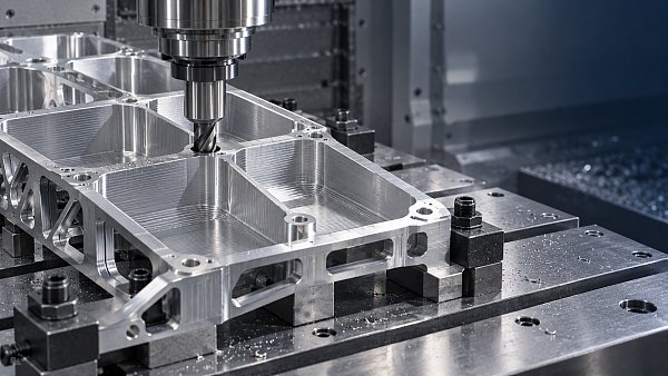
A practical route may include roughing, controlled release and inspection, re-establishment of the setup, semi-finishing, and final finishing. Each additional setup adds handling and datum-transfer uncertainty, so use these stages where they address measurable movement rather than adding them automatically.
Support the part without machining a clamped-in shape
A fixture should locate the component repeatably and resist machining loads without imposing an unacceptable shape. If a blank rocks on its supports, tightening the clamps until it sits flat stores elastic deformation in the workpiece. Machining then creates accurate surfaces on a distorted body; release exposes the error.
Seat the part on clean, defined locating surfaces and check for chips, burrs, and unsupported gaps. Position clamps over or near load-bearing supports wherever practical. A clamp acting on a thin floor between supports can bend that floor even when its force seems modest.
Adjustable supports should contact the seated component without jacking it away from its datums. Hydraulic or mechanical work supports can improve local stiffness, but their contact force and locking behavior must suit the feature. A support that pushes a flexible wall into position creates another source of preload.
Vacuum fixtures can distribute holding force over a broad area, yet they are not inherently distortion-free. Available force depends on pressure differential and effective sealed area, while unsupported pockets or seal locations can permit local bending. Check both resistance to cutting loads and deformation under vacuum before relying on the arrangement for thin floors.
Temporary backing, sacrificial ribs, or removable filler can help with difficult geometries when the approved process permits them. Consider removal access, contamination, chemical compatibility, and the possibility of damaging the finished feature. Support is only useful if it can be removed without compromising the part.
Match the cut to the stiffness remaining at that moment
The cutting conditions that work during roughing may become unstable after surrounding stock disappears. As the wall gets thinner, its response changes. In a simplified bending model, stiffness varies with the cube of thickness: halving thickness reduces bending stiffness to roughly one-eighth, with other factors unchanged. Actual pocket geometry is more complex, but the relationship explains why the last operations need different treatment.
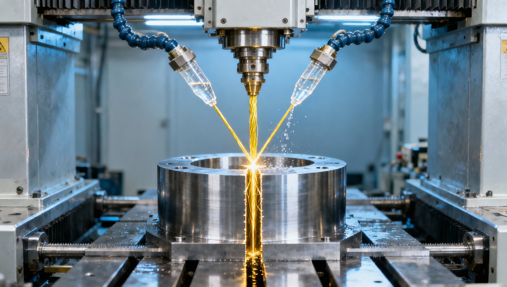
Use sharp, aluminum-appropriate cutting edges and minimize tool overhang. Check holder condition and runout, particularly with small cutters: uneven tooth loading can produce variable forces and poor wall thickness consistency. A larger-diameter or shorter-reach tool may improve rigidity, provided access and engagement remain suitable.
Low radial engagement can reduce instantaneous load, but increasing axial engagement is not automatically beneficial. A long contact length against an unsupported wall can excite vibration or produce substantial distributed deflection. Select both engagements around the supported wall height, tool reach, and observed stability.
Reducing feed excessively can promote rubbing rather than clean cutting. Maintain an effective chip thickness appropriate to the cutter and engagement, and use tool-supplier guidance as a starting point. If chatter appears, changing spindle speed or engagement may be more effective than repeatedly lowering feed.
Control entry, exit, and corner engagement as carefully as the straight cut. A stable wall pass can become unstable when the cutter enters a tight internal corner and engagement rises sharply. Rest machining, suitable corner toolpaths, and separate finishing operations can prevent that localized load spike.
Evaluate cutting direction against the fixture and feature geometry. Climb milling is widely used on CNC equipment, but the resulting force direction still needs to be understood: a pass may press a wall toward support or encourage it to move away. There is no reliable rule that one direction eliminates thin-wall deflection in every setup.
Keep heat and chip accumulation out of the diagnosis
Aluminum’s thermal expansion is large enough to matter at tight tolerances. Using an approximate expansion coefficient of 23 µm/m/°C, a 300 mm dimension changes by about 0.035 mm over a uniform 5°C temperature change. This is an illustrative calculation, not a machining allowance; the applicable alloy and inspection conditions determine the actual assessment.
Uneven heating is more troublesome than uniform expansion because it can temporarily bow a floor or wall. Maintain consistent coolant delivery and temperature control, and avoid allowing chips to pack into deep pockets. Recut chips can damage the surface, increase local loading, and disrupt an otherwise stable finishing operation.
A warm part that measures correctly against a cold fixture is not necessarily correct at the specified reference condition. Allow the component, fixture, and measuring equipment to reach an appropriate thermal condition before making offset changes based on small deviations.
Use release measurements to decide the next adjustment
On-machine probing is useful for tracking stock and movement, but it reports geometry within the current restraint system. It cannot establish free-state conformity by itself. Conversely, a flexible part placed arbitrarily on a surface plate may sag differently from the drawing’s required inspection setup.
Follow the specified datums, support locations, and restrained or unrestrained inspection requirements. Where those conditions are unclear, resolve them before machining to a tight tolerance. Support and probe forces must not meaningfully distort the feature being measured.
For a new or unstable route, record selected dimensions after roughing, after release and thermal stabilization, and after finishing under the required inspection conditions. Include clamp settings, tool identity, stock orientation, and temperature observations. This creates a basis for changing one influential variable rather than compensating blindly.
If geometry changes mainly on unclamping, investigate seating and preload before changing offsets. If movement follows heavy stock removal, revise the roughing sequence or material route. If a repeat pass removes more material, investigate elastic deflection—but do not make repeated “spring passes” the default cure. Additional passes can rub, heat the wall, and conceal an unstable process.
The release condition is the decisive check. A reliable process reaches the required geometry without depending on fixture force to hide movement, and its intermediate measurements explain why the result repeats.
Get weekly intelligence in your inbox.
No noise. No sponsored content. Pure intelligence.
 Oct 22, 2026Mitsubishi Electric Develops Industry-First Humanoid Robot–CNC Machining SystemMitsubishi Electric Develops Industry-First Humanoid Robot–CNC Machining System
 Oct 22, 2026Aerospace Aluminum Machining: How to Control Distortion in Thin-Wall PartsAerospace Aluminum Machining: How to Control Distortion in Thin-Wall Parts
 Oct 21, 2026Genesis Energy commissions 200 MWh battery storage system at HuntlyGenesis Energy commissions 200 MWh battery storage system at Huntly
 Oct 21, 2026Buying AMI Smart Meters Wholesale: Compatibility Checks and Total CostsBuying AMI Smart Meters Wholesale: Compatibility Checks and Total Costs
 Oct 20, 2026Werner Enterprises Issues Q3 Earnings Warning as Costs RiseWerner Enterprises Issues Q3 Earnings Warning as Costs Rise
 Oct 20, 2026Are Digital Twins Viable for SMEs? Costs, Use Cases, and Data RequirementsAre Digital Twins Viable for SMEs? Costs, Use Cases, and Data Requirements
 Oct 19, 2026Choosing a Wholesale Servo Motor Exporter: Traceability and Warranty ChecksChoosing a Wholesale Servo Motor Exporter: Traceability and Warranty Checks
 Oct 18, 2026Syringe Manufacturing Equipment: Evaluating Throughput and Assembly AccuracySyringe Manufacturing Equipment: Evaluating Throughput and Assembly Accuracy
 Oct 17, 2026Air Freight Forwarding Services: How to Compare Quotes for Urgent ShipmentsAir Freight Forwarding Services: How to Compare Quotes for Urgent Shipments
 Oct 16, 2026Wholesale Solar Panels: How to Compare Bulk Quotes by Total Landed CostWholesale Solar Panels: How to Compare Bulk Quotes by Total Landed Cost
 Oct 15, 2026Supply Chain Intelligence for Sourcing: How to Vet New SuppliersSupply Chain Intelligence for Sourcing: How to Vet New Suppliers
 Oct 14, 2026How skills shortages slow smart manufacturing in Southeast AsiaHow skills shortages slow smart manufacturing in Southeast Asia
 Oct 14, 2026How CNC wire-cut machining maintains tight tolerances in thick partsHow CNC wire-cut machining maintains tight tolerances in thick parts
 Oct 14, 2026Can automated feeding stabilize metal forming in smart factories?Can automated feeding stabilize metal forming in smart factories?
 Oct 14, 2026Can CT inspection detect internal defects in metal additive parts?Can CT inspection detect internal defects in metal additive parts?
 Oct 14, 2026When does additive manufacturing reduce lead time for spare parts?When does additive manufacturing reduce lead time for spare parts?
 Oct 14, 2026How production volume affects ROI on an automated painting lineHow production volume affects ROI on an automated painting line
 Oct 14, 2026What data does manufacturing bottleneck analysis consulting need?What data does manufacturing bottleneck analysis consulting need?
 Oct 14, 2026When should you hire a consultant for manufacturing bottlenecks?When should you hire a consultant for manufacturing bottlenecks?
 Oct 14, 2026How Do You Measure AI Adoption Maturity in a Traditional Factory?How Do You Measure AI Adoption Maturity in a Traditional Factory?
 Oct 14, 2026Are Chinese AI-Assisted Surgical Devices Gaining Global Trust?Are Chinese AI-Assisted Surgical Devices Gaining Global Trust?
 Oct 14, 2026What Happens When Warehouse Robots Need Software Updates Mid-Operation?What Happens When Warehouse Robots Need Software Updates Mid-Operation?
 Oct 14, 2026How Do Plants Calculate Real Savings from Energy-Efficient Equipment?How Do Plants Calculate Real Savings from Energy-Efficient Equipment?
 Oct 14, 2026Are Digital Twins Only for Large Enterprises, or Can SMEs Use Them?Are Digital Twins Only for Large Enterprises, or Can SMEs Use Them?
 Oct 14, 2026What Are the Common Failure Modes in Legacy Industrial Control Systems?What Are the Common Failure Modes in Legacy Industrial Control Systems?
 Oct 14, 2026Do Electronic Component Distributors Add Value or Just Markup?Do Electronic Component Distributors Add Value or Just Markup?
 Oct 14, 2026What ESG Requirements Apply to Solar PV Exporters Selling to Europe?What ESG Requirements Apply to Solar PV Exporters Selling to Europe?