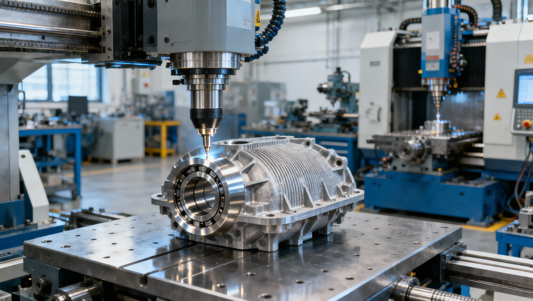
Can CT inspection detect internal defects in metal additive parts?
Yes—industrial computed tomography (CT) can detect internal porosity, lack-of-fusion defects, and some cracks in metal additive parts without cutting them open. It can also show where a defect sits, how it connects with nearby voids, and whether it approaches a surface or an internal channel. That makes CT useful for investigating build quality and assessing components whose internal features are difficult to inspect by other methods.
Its capability has limits. A scan that detects pores in a small aluminum component may struggle with narrow cracks inside a thick nickel-alloy part. For quality and safety teams, the useful question is whether the inspection can reliably detect the defects that matter in the actual component. Part release requires a demonstrated detection capability and an engineering acceptance rule; a clear-looking 3D reconstruction alone does not provide either.
Which internal defects can CT reveal?
CT reconstructs a volume from X-ray projections taken at different angles. Differences in X-ray attenuation allow the reconstructed image to distinguish bulk metal from voids and, under suitable conditions, other materials. Inspectors can examine cross-sectional slices and measure indications in three dimensions, avoiding the overlap that complicates conventional radiographic images.
For internal defect inspection of metal additive parts, the most useful findings generally fall into three groups:
- Porosity: Gas pores and larger process-related cavities can appear as low-attenuation regions. CT can characterize their size, distribution, clustering, and distance from a surface, provided the inspection has sufficient sensitivity.
- Lack of fusion: Incomplete bonding between tracks or layers can produce irregular, flattened, or interconnected voids. Their shape and position can be more significant than their contribution to total porosity.
- Cracks: Open cracks may be visible when their opening, extent, contrast, and orientation support detection. Very tight cracks can remain undetected even when their overall length is substantial.
Defect morphology can suggest a process mechanism, but CT appearance alone does not always establish the cause. An irregular cavity may be consistent with lack of fusion, for example, while confirmation may require metallography and a review of build parameters. Automated software labels should therefore be treated as classifications requiring validation, especially when they influence acceptance decisions.
CT also has boundaries outside void detection. An inclusion may be visible if its attenuation differs sufficiently from the surrounding alloy. An inclusion with similar attenuation may be difficult to distinguish. Microstructure, residual stress, chemical composition, and metallurgical bond quality cannot be established simply by finding no visible voids.
Internal passages present a related challenge. CT can reveal blocked channels and accumulations of trapped powder, but partially filled regions may be harder to segment than an empty passage. A geometrically open channel also does not establish acceptable flow or cleanliness. Those requirements may need separate functional testing.
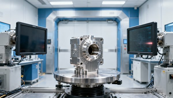
Why voxel size does not establish the detection limit
A supplier may describe an inspection by its voxel size—the dimensions of each element in the reconstructed volume. This is useful information, but it is not a guaranteed minimum detectable defect size. Effective spatial resolution also depends on the focal spot, detector performance, geometric magnification, motion, reconstruction settings, and image noise.
A feature occupying only part of a voxel contributes an averaged signal. This partial-volume effect can blur a small pore or a narrow crack into the surrounding metal. Some features below the nominal voxel dimensions may influence the image, but their presence, shape, and size cannot automatically be measured reliably. Conversely, a feature spanning several voxels may remain difficult to detect if contrast is poor or artifacts obscure it.
Detecting a feature and measuring it accurately are separate capabilities. A scan may reveal a small cavity while providing insufficient information to determine whether its dimensions fall just above or below an acceptance threshold. Near that threshold, measurement uncertainty needs to be part of the disposition process.
Material and geometry constrain the scan
X-ray penetration depends on alloy composition, density, beam energy, and the thickness traversed by the beam. Thick sections and strongly attenuating alloys can reduce the useful signal reaching the detector. Within one component, thin walls may produce good images while a heavy boss or flange creates a difficult inspection region.
Increasing energy can improve penetration, but it does not guarantee better defect sensitivity. Equipment choices and exposure settings involve tradeoffs among penetration, contrast, focal-spot size, noise, and acquisition time. The procedure needs to balance these factors for the target defects.
Part size also limits achievable magnification and coverage. A small specimen may be positioned for high-resolution imaging, while a complete component requires a larger field of view. Scanning a selected region can improve local detail, but the report must identify what volume was examined and what remains outside the qualified inspection coverage.
Beam hardening, scatter, and photon starvation can create shading, streaks, or false indications. Correction software may reduce these effects, but residual artifacts can still conceal defects or distort their measured boundaries. A visually smooth reconstruction should be checked for evidence that processing has preserved relevant indications.
Cracks require a different sensitivity argument
A rounded pore presents a void volume in several directions. A planar crack may be long but have a very small opening. Its visibility depends on how the crack interacts with the projection directions and how reconstruction resolves its thin geometry.
CT collects many views, which helps characterize three-dimensional features, but sensitivity to thin planar flaws remains orientation-dependent. A procedure demonstrated on spherical pores cannot automatically be claimed to detect tight cracks or flattened lack-of-fusion defects of similar reported length. Validation must represent the flaw types that could drive failure.
How to turn CT findings into an acceptance decision
A component can have low total porosity and still contain a damaging defect near a highly stressed surface. Another component may contain more distributed porosity in a region with lower structural demand. A single bulk-density or porosity percentage therefore provides limited evidence for safety-critical release.
Acceptance criteria should reflect the service conditions and failure modes. For a fatigue-loaded component, defect location, shape, and proximity to the surface may strongly influence significance. For a pressure-containing part, connected voids and paths through the wall may deserve particular attention. Leakage testing can provide additional evidence because a CT image may not resolve every narrow connection.
Engineering requirements may include maximum individual defect dimensions, limits on clusters, minimum distance from a surface, restrictions within designated critical zones, and allowable local porosity. The chosen metrics should connect to the component’s design basis, material qualification, and applicable customer or regulatory requirements. They should be agreed before inspecting production parts.
The reported definition of “defect size” also needs to be explicit. Maximum three-dimensional extent, equivalent spherical diameter, and projected area describe different attributes. An equivalent diameter can obscure the significance of a thin, elongated defect. Reports should use the metric specified by the acceptance rule and retain enough geometric information for engineering review.
Segmentation introduces another source of uncertainty. Software separates suspected voids from surrounding metal using thresholds or other classification methods. Changing those settings can alter measured volume, merge neighboring pores, or remove small indications. Near rough surfaces and thin walls, separating an internal defect from the external background becomes especially difficult.
A defensible analysis procedure records the segmentation method, minimum reporting threshold, treatment of connected indications, excluded regions, and review process. Borderline findings should trigger a defined disposition route, such as additional inspection or engineering assessment. Repeatedly changing analysis settings until a part passes undermines the acceptance decision.
Standards guide the method; specifications define the limits
ASTM E1441 provides guidance on computed tomography imaging, and ASTM E1570 addresses CT examination practice. The ISO 15708 series covers industrial computed tomography for nondestructive testing. These documents can help structure a CT procedure and its technical controls.
They do not establish a universal acceptable pore size for every additively manufactured metal component. The applicable drawing, product specification, qualification plan, and contractual requirements must supply or reference the acceptance criteria. The required editions and any sector-specific provisions should be identified in the inspection documentation.
For regulated or safety-critical applications, the inspection organization must also meet the relevant personnel, procedure approval, recordkeeping, and oversight requirements. A statement that a scan follows a CT standard is insufficient if it leaves the acceptance basis and demonstrated sensitivity undefined.
What evidence should quality teams require before relying on CT?
Qualification should begin with a component-specific inspection objective. Define the critical regions, expected flaw types, smallest relevant indications, required coverage, and intended decision. Process development may need detailed characterization of representative samples; production release may require repeatable detection against a fixed acceptance specification.
The strongest capability evidence comes from representative material and geometry. Reference samples should challenge the scan with relevant attenuation paths and flaw characteristics. Artificial features can help assess performance, but a drilled hole may not reproduce the visibility of a tight crack or an irregular lack-of-fusion defect.
Where practical, CT findings can be compared with destructive sectioning or metallography during qualification. This comparison can reveal missed features, segmentation bias, and incorrect classifications. Sectioning itself requires careful planning because a limited number of planes may miss defects visible elsewhere in the CT volume.
For high-consequence applications, a probability-of-detection study may be appropriate or required. Such a study addresses the likelihood of finding specified flaws under defined conditions. A single successful scan of a reference defect demonstrates visibility in that instance; it does not establish detection reliability across production variability.
Before approving an inspection provider or an internal procedure, quality teams should seek clear answers to these questions:
- What flaw types and sizes has the procedure demonstrated it can detect in the relevant alloy and geometry?
- Does that capability extend to every critical region, including the thickest sections and artifact-prone areas?
- How are detection limits, measurement uncertainty, and borderline results handled?
- Which acquisition, reconstruction, and analysis settings are controlled, and what changes require requalification?
- Does the report link each disposition to the applicable acceptance criterion and component identity?
Production conditions deserve attention during this review. Scanning several parts together can change attenuation, scatter, and magnification. A faster scan may increase noise. A fixture or orientation change can alter artifacts in a critical region. Any departure from the qualified setup needs an assessment of its effect on inspection capability.
Inspection timing also matters. Heat treatment, hot isostatic pressing, and machining can change defect geometry or remove material around previously internal indications. If release depends on the final condition, the inspection plan should address that condition. A pre-treatment scan remains useful for process control, but its findings cannot automatically represent the finished component.
CT is a strong choice when internal access is limited and three-dimensional defect location matters. It may need support from penetrant testing for accessible surface-breaking flaws, ultrasonic methods for suitable geometries and flaw orientations, leak testing for containment, or destructive examination during qualification. Each method should address a defined gap in the inspection evidence.
A credible release statement is therefore specific: the defined regions were examined using a qualified procedure, and the reported indications met the specified acceptance criteria within that procedure’s demonstrated capability. That gives quality and safety teams an actionable basis for disposition while keeping “no reportable indications” from becoming an unsupported claim that the part contains no defects.
Get weekly intelligence in your inbox.
No noise. No sponsored content. Pure intelligence.
 Oct 22, 2026Mitsubishi Electric Develops Industry-First Humanoid Robot–CNC Machining SystemMitsubishi Electric Develops Industry-First Humanoid Robot–CNC Machining System
 Oct 22, 2026Aerospace Aluminum Machining: How to Control Distortion in Thin-Wall PartsAerospace Aluminum Machining: How to Control Distortion in Thin-Wall Parts
 Oct 21, 2026Genesis Energy commissions 200 MWh battery storage system at HuntlyGenesis Energy commissions 200 MWh battery storage system at Huntly
 Oct 21, 2026Buying AMI Smart Meters Wholesale: Compatibility Checks and Total CostsBuying AMI Smart Meters Wholesale: Compatibility Checks and Total Costs
 Oct 20, 2026Werner Enterprises Issues Q3 Earnings Warning as Costs RiseWerner Enterprises Issues Q3 Earnings Warning as Costs Rise
 Oct 20, 2026Are Digital Twins Viable for SMEs? Costs, Use Cases, and Data RequirementsAre Digital Twins Viable for SMEs? Costs, Use Cases, and Data Requirements
 Oct 19, 2026Choosing a Wholesale Servo Motor Exporter: Traceability and Warranty ChecksChoosing a Wholesale Servo Motor Exporter: Traceability and Warranty Checks
 Oct 18, 2026Syringe Manufacturing Equipment: Evaluating Throughput and Assembly AccuracySyringe Manufacturing Equipment: Evaluating Throughput and Assembly Accuracy
 Oct 17, 2026Air Freight Forwarding Services: How to Compare Quotes for Urgent ShipmentsAir Freight Forwarding Services: How to Compare Quotes for Urgent Shipments
 Oct 16, 2026Wholesale Solar Panels: How to Compare Bulk Quotes by Total Landed CostWholesale Solar Panels: How to Compare Bulk Quotes by Total Landed Cost
 Oct 15, 2026Supply Chain Intelligence for Sourcing: How to Vet New SuppliersSupply Chain Intelligence for Sourcing: How to Vet New Suppliers
 Oct 14, 2026How skills shortages slow smart manufacturing in Southeast AsiaHow skills shortages slow smart manufacturing in Southeast Asia
 Oct 14, 2026How CNC wire-cut machining maintains tight tolerances in thick partsHow CNC wire-cut machining maintains tight tolerances in thick parts
 Oct 14, 2026Can automated feeding stabilize metal forming in smart factories?Can automated feeding stabilize metal forming in smart factories?
 Oct 14, 2026Can CT inspection detect internal defects in metal additive parts?Can CT inspection detect internal defects in metal additive parts?
 Oct 14, 2026When does additive manufacturing reduce lead time for spare parts?When does additive manufacturing reduce lead time for spare parts?
 Oct 14, 2026How production volume affects ROI on an automated painting lineHow production volume affects ROI on an automated painting line
 Oct 14, 2026What data does manufacturing bottleneck analysis consulting need?What data does manufacturing bottleneck analysis consulting need?
 Oct 14, 2026When should you hire a consultant for manufacturing bottlenecks?When should you hire a consultant for manufacturing bottlenecks?
 Oct 14, 2026How Do You Measure AI Adoption Maturity in a Traditional Factory?How Do You Measure AI Adoption Maturity in a Traditional Factory?
 Oct 14, 2026Are Chinese AI-Assisted Surgical Devices Gaining Global Trust?Are Chinese AI-Assisted Surgical Devices Gaining Global Trust?
 Oct 14, 2026What Happens When Warehouse Robots Need Software Updates Mid-Operation?What Happens When Warehouse Robots Need Software Updates Mid-Operation?
 Oct 14, 2026How Do Plants Calculate Real Savings from Energy-Efficient Equipment?How Do Plants Calculate Real Savings from Energy-Efficient Equipment?
 Oct 14, 2026Are Digital Twins Only for Large Enterprises, or Can SMEs Use Them?Are Digital Twins Only for Large Enterprises, or Can SMEs Use Them?
 Oct 14, 2026What Are the Common Failure Modes in Legacy Industrial Control Systems?What Are the Common Failure Modes in Legacy Industrial Control Systems?
 Oct 14, 2026Do Electronic Component Distributors Add Value or Just Markup?Do Electronic Component Distributors Add Value or Just Markup?
 Oct 14, 2026What ESG Requirements Apply to Solar PV Exporters Selling to Europe?What ESG Requirements Apply to Solar PV Exporters Selling to Europe?