How CNC wire-cut machining maintains tight tolerances in thick parts
CNC wire-cut machining maintains tight tolerances in thick parts by controlling the wire’s position throughout the cut, stabilizing the discharge gap, and removing finishing stock under repeatable conditions. Axis positioning accuracy alone cannot guarantee a straight wall: a wire can follow the programmed path at the guides while bending inside the workpiece. A successful setup therefore has to control size, taper, and profile variation across the full thickness.
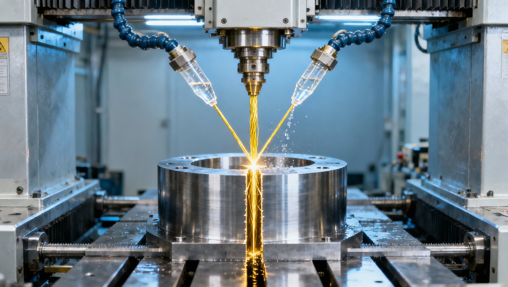
For electrically conductive materials, wire electrical discharge machining (EDM) removes metal without conventional cutting forces. However, discharge activity, flushing pressure, wire motion, and thermal changes still affect geometry. Reliable cnc wire-cut machining for tight tolerances begins with separating these effects, because an offset correction that fixes the measured opening at one surface can leave an unacceptable error deeper in the part.
Separate dimensional error from through-thickness shape error
A thick component can meet its specified width at the top and still have tapered or bowed walls. Taper produces a progressive change between the upper and lower faces. A bowed profile has a different shape near the middle, even when the two ends agree. Measuring only the accessible faces can therefore miss the largest deviation.
This distinction determines the next adjustment. A nearly uniform size error along the thickness points toward the effective wire offset, discharge gap, or dimensional reference. A consistent slope calls for investigation of guide alignment, programmed taper, and unequal cutting conditions. A middle-section deviation directs attention toward wire deflection and debris evacuation. These are diagnostic starting points; the measured pattern must be compared with the actual setup.
Establish the acceptance criteria before cutting. Size tolerance, wall straightness, perpendicularity, and profile tolerance describe different requirements. The drawing’s datum system also matters: a wall that is straight can still be incorrectly oriented relative to the locating surface. Surface roughness alone does not establish any of these geometric conditions.
The wire behaves differently inside a long cut
The upper and lower guides define the wire’s supported path, but the wire between them remains flexible. Thick workpieces increase the length exposed to discharge activity and fluid forces. During contouring, the wire can lag behind the commanded motion, particularly where direction changes rapidly. This makes corners and small radii more demanding than long straight sections.
Higher wire tension reduces deflection within the limits of the selected wire and machine. Excessive tension reduces the margin against breakage, especially when discharge heating or unstable cutting has weakened the wire. Use the machine’s technology data for the actual wire diameter, wire type, material, and thickness, then evaluate the resulting geometry. A tension value copied from a thinner job is not a validated thick-part setting.
Guide condition and guide-to-workpiece distance deserve equal attention. Worn or contaminated guides compromise wire positioning. Keeping the guides close to the workpiece reduces unsupported length where the setup permits it, but nozzle clearance must accommodate clamps, steps, and movement. Verify vertical alignment with the machine’s prescribed procedure before compensating for taper in the program.
Wire feed renews the electrode as it passes through the cut. An unsuitable feed setting changes wire heating and wear, which affects process consistency. Tension, feed, and discharge energy work together; adjusting one while ignoring the others can exchange a geometric error for frequent breaks or unstable machining.
Flushing must clear debris without displacing the wire
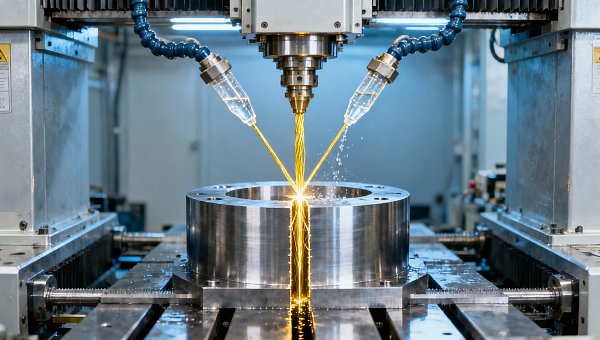
As thickness increases, debris has a longer escape path from the active machining zone. Accumulated particles disturb electrical conditions and encourage localized arcing or short circuits. The machine’s servo then changes feed or retracts to recover the gap. Repeated recovery events can leave uneven erosion and visible bands on the wall.
Increasing flushing pressure is not an automatic cure. Strong or asymmetric flow can deflect the wire, especially when one nozzle seals effectively and the other does not. A fixture opening, stepped surface, or nearby edge can change the flow pattern even though the pressure setting remains constant. Evaluate nozzle proximity, sealing conditions, and the available debris exit path together.
Submerged machining provides a more consistent surrounding dielectric environment, but immersion does not ensure effective flushing inside a deep kerf. Internal corners, narrow slots, and partially enclosed profiles still restrict fluid exchange. Where close nozzle positioning is impossible, use cutting conditions intended for poor flushing rather than forcing a setting developed for a well-sealed straight cut.
The flushing conditions also change as the cut opens or a slug becomes free. A sudden loss of confinement alters fluid flow and can coincide with a witness mark or wire break. Plan slug support and the final separation location so that movement cannot pinch the wire or damage the finished surface.
Use discharge settings that match the available gap conditions
Rough cutting removes most of the material, but it must leave a controllable surface and enough stock for finishing. Excessive discharge energy increases thermal damage and wire loading. If debris removal cannot keep pace, faster nominal settings produce repeated instability rather than useful cutting speed.
Pulse energy, pulse spacing, and servo control influence how the discharge gap develops. Longer recovery intervals can help restore dielectric conditions in a difficult cut, while lower energy reduces the load on the wire. These changes also affect removal rate and the effective gap, so the resulting dimensions require verification. Machine setting names and scales differ; identical displayed values on different controls do not establish equivalent cutting conditions.
Watch the relationship between feed behavior and geometry. Frequent servo slowdowns at a particular depth or contour feature suggest a local process limitation. A stable straight cut followed by distorted corners points toward contour dynamics or corner-specific conditions rather than a global size offset.
Corner control reduces feed or modifies discharge conditions as the wire changes direction. Excessive speed allows wire lag to alter the profile, while unnecessary dwell can increase local erosion. Use the control’s supported corner strategy and confirm the actual radius or intersection on the finished part.
Skim cuts need consistent stock, not just additional passes
Skim cutting improves dimensional control by removing a smaller allowance at lower discharge energy. With less material to erode, the wire experiences a different load and the wall can be refined more accurately. The benefit depends on leaving suitable, reasonably uniform stock after roughing.
An insufficient allowance leaves some regions without a continuous finishing cut. An excessive allowance makes the supposed finishing pass behave more like another rough cut, increasing wire deflection and discharge instability. Thick-part technology settings should therefore specify both the pass sequence and its associated offsets. Changing the number of passes without revisiting the allowance distribution can undermine the intended finish.
The programmed compensation includes the wire radius and the effective discharge gap for that pass. Roughing and finishing gaps differ. Reusing a roughing offset for a skim cut introduces a predictable size problem even when the axes and guides are accurately aligned.
Finishing flow conditions also differ from roughing. Once the profile has opened, flushing acts on an exposed wall rather than a confined slot. Apply the machine’s finishing strategy for pressure, direction, and offset. If measurement shows a correct average size with remaining bow, further offset changes will move the wall without necessarily straightening it.
Thermal stability and stress release can resemble cutting errors
Temperature changes affect the workpiece, machine structure, and measurement system. A thick component has substantial thermal mass, so its surface temperature does not necessarily represent its interior. Cutting immediately after transferring a part from a different temperature environment can create a changing dimensional condition during the job.
Keep the dielectric temperature controlled, allow the machine to reach its specified stable operating condition, and let the workpiece approach thermal equilibrium. Dimensional inspection also requires an established temperature condition. Comparing a recently machined part with a reference measured under different conditions can prompt an unnecessary compensation change.
Dielectric conductivity must remain within the range required by the selected process. On water-based machines, filtration and deionization affect electrical stability. Conductivity, temperature, and filter condition should be considered together when discharge behavior changes across otherwise similar jobs.
Residual stress introduces a separate problem. Removing a contour from rolled, forged, welded, or heat-treated stock can redistribute stress and move the remaining material. EDM’s lack of conventional cutting force does not prevent this movement. Where the material route permits it, a rough cut followed by stabilization and finishing can reduce the effect. The sequence must suit the material and drawing requirements.
Clamping can conceal the same issue. A part held flat by excessive fixture force may move after release. Use support that prevents movement during cutting without forcing the workpiece into an artificial shape, and verify critical geometry in the specified inspection condition.
Read the error pattern before changing compensation
Make a controlled adjustment to one suspected cause, then compare the same measurement locations. Simultaneously changing tension, energy, pressure, and compensation removes the evidence needed to identify which change corrected the problem.
Qualify the full thickness before releasing the setup
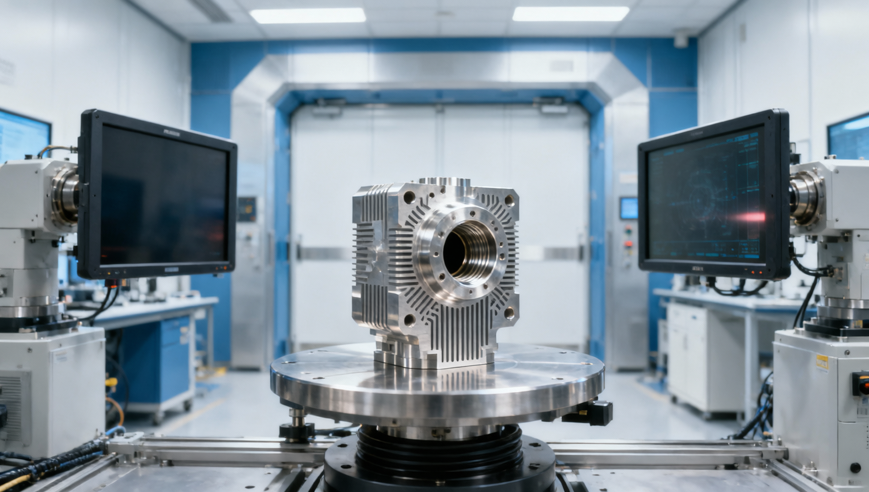
Inspection should sample geometry near both faces and at intermediate depths wherever access allows. A coordinate measuring machine can assess wall position, orientation, and straightness using an appropriate probing strategy. Stylus reach, stiffness, tip size, and access restrictions affect measurement reliability. A probe that cannot reach the middle cannot prove that the middle meets tolerance.
Top-face optical inspection is useful for accessible contour dimensions, but it does not establish through-thickness form. For inaccessible features, choose a validated method suited to the geometry, or use a representative qualification piece that permits deeper inspection. A witness piece must reproduce the relevant thickness, material condition, wire, flushing arrangement, and pass sequence; a thin coupon does not test the same wire behavior.
Record actual dimensions against the specified datums, along with the measurement condition and uncertainty appropriate to the tolerance. Retain the wire specification, technology settings, offsets, nozzle arrangement, and fixture details with the accepted setup. Subsequent production then has a defined process reference, and any drift can be compared with the conditions under which the full-thickness geometry was verified.
Get weekly intelligence in your inbox.
No noise. No sponsored content. Pure intelligence.
 Oct 22, 2026Mitsubishi Electric Develops Industry-First Humanoid Robot–CNC Machining SystemMitsubishi Electric Develops Industry-First Humanoid Robot–CNC Machining System
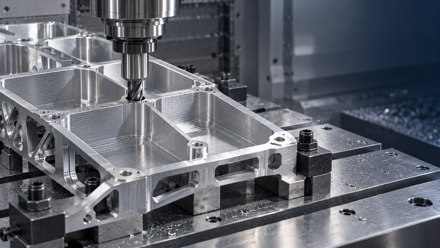
 Oct 22, 2026Aerospace Aluminum Machining: How to Control Distortion in Thin-Wall PartsAerospace Aluminum Machining: How to Control Distortion in Thin-Wall Parts
 Oct 21, 2026Genesis Energy commissions 200 MWh battery storage system at HuntlyGenesis Energy commissions 200 MWh battery storage system at Huntly
 Oct 21, 2026Buying AMI Smart Meters Wholesale: Compatibility Checks and Total CostsBuying AMI Smart Meters Wholesale: Compatibility Checks and Total Costs
 Oct 20, 2026Werner Enterprises Issues Q3 Earnings Warning as Costs RiseWerner Enterprises Issues Q3 Earnings Warning as Costs Rise
 Oct 20, 2026Are Digital Twins Viable for SMEs? Costs, Use Cases, and Data RequirementsAre Digital Twins Viable for SMEs? Costs, Use Cases, and Data Requirements
 Oct 19, 2026Choosing a Wholesale Servo Motor Exporter: Traceability and Warranty ChecksChoosing a Wholesale Servo Motor Exporter: Traceability and Warranty Checks
 Oct 18, 2026Syringe Manufacturing Equipment: Evaluating Throughput and Assembly AccuracySyringe Manufacturing Equipment: Evaluating Throughput and Assembly Accuracy
 Oct 17, 2026Air Freight Forwarding Services: How to Compare Quotes for Urgent ShipmentsAir Freight Forwarding Services: How to Compare Quotes for Urgent Shipments
 Oct 16, 2026Wholesale Solar Panels: How to Compare Bulk Quotes by Total Landed CostWholesale Solar Panels: How to Compare Bulk Quotes by Total Landed Cost
 Oct 15, 2026Supply Chain Intelligence for Sourcing: How to Vet New SuppliersSupply Chain Intelligence for Sourcing: How to Vet New Suppliers
 Oct 14, 2026How skills shortages slow smart manufacturing in Southeast AsiaHow skills shortages slow smart manufacturing in Southeast Asia
 Oct 14, 2026How CNC wire-cut machining maintains tight tolerances in thick partsHow CNC wire-cut machining maintains tight tolerances in thick parts
 Oct 14, 2026Can automated feeding stabilize metal forming in smart factories?Can automated feeding stabilize metal forming in smart factories?
 Oct 14, 2026Can CT inspection detect internal defects in metal additive parts?Can CT inspection detect internal defects in metal additive parts?
 Oct 14, 2026When does additive manufacturing reduce lead time for spare parts?When does additive manufacturing reduce lead time for spare parts?
 Oct 14, 2026How production volume affects ROI on an automated painting lineHow production volume affects ROI on an automated painting line
 Oct 14, 2026What data does manufacturing bottleneck analysis consulting need?What data does manufacturing bottleneck analysis consulting need?
 Oct 14, 2026When should you hire a consultant for manufacturing bottlenecks?When should you hire a consultant for manufacturing bottlenecks?
 Oct 14, 2026How Do You Measure AI Adoption Maturity in a Traditional Factory?How Do You Measure AI Adoption Maturity in a Traditional Factory?
 Oct 14, 2026Are Chinese AI-Assisted Surgical Devices Gaining Global Trust?Are Chinese AI-Assisted Surgical Devices Gaining Global Trust?
 Oct 14, 2026What Happens When Warehouse Robots Need Software Updates Mid-Operation?What Happens When Warehouse Robots Need Software Updates Mid-Operation?
 Oct 14, 2026How Do Plants Calculate Real Savings from Energy-Efficient Equipment?How Do Plants Calculate Real Savings from Energy-Efficient Equipment?
 Oct 14, 2026Are Digital Twins Only for Large Enterprises, or Can SMEs Use Them?Are Digital Twins Only for Large Enterprises, or Can SMEs Use Them?
 Oct 14, 2026What Are the Common Failure Modes in Legacy Industrial Control Systems?What Are the Common Failure Modes in Legacy Industrial Control Systems?
 Oct 14, 2026Do Electronic Component Distributors Add Value or Just Markup?Do Electronic Component Distributors Add Value or Just Markup?
 Oct 14, 2026What ESG Requirements Apply to Solar PV Exporters Selling to Europe?What ESG Requirements Apply to Solar PV Exporters Selling to Europe?