How to Select a DIN Rail Smart Meter for Multi-Circuit Energy Monitoring
How to Select a DIN Rail Smart Meter for Multi-Circuit Energy Monitoring
Selecting a DIN rail smart meter for multi-circuit energy monitoring requires more than comparing a headline accuracy class or choosing the model with the largest number of current-transformer inputs. The right device must match the electrical architecture, the data users actually need, the available panel space, and the software environment that will receive the measurements.
For a facility manager, the objective may be to identify which tenants, production lines, or HVAC loads are driving peak demand. For an industrial engineering team, it may be to separate energy use by machine cell, detect abnormal loads, or support internal carbon accounting. In a commercial retrofit, the main constraint may simply be installing meaningful monitoring without replacing a crowded distribution board.
A multi-circuit meter can consolidate monitoring that would otherwise require multiple single-point meters. That consolidation is valuable, but it also creates new design questions: how circuits are grouped, whether voltage references are shared correctly, how current transformers are selected, and whether the resulting data remains understandable after installation. A meter that fits the rail but does not fit the measurement plan is rarely a cost-effective choice.
Start with the monitoring question, not the meter catalogue
Before comparing products, define what the system must make visible. “Monitor energy use” is too broad to guide selection. A practical scope identifies the circuits to be measured, the reporting interval, the users of the data, and the decisions they expect to make from it.
For example, monitoring outgoing circuits in a lighting panel is different from monitoring several three-phase motor feeders. A branch-circuit application may prioritize a high channel count and compact wiring. A process plant may need real-time power, phase imbalance, demand values, harmonics, or power-quality indicators. Where solar generation, battery systems, generators, or changing power direction are involved, the meter must also handle import and export energy in a way that aligns with the reporting model.
It is useful to divide requirements into three layers: operational monitoring, cost allocation, and formal billing or compliance. Operational monitoring often tolerates a different accuracy approach from tenant billing. If readings will support invoices, contractual allocation, or regulatory reporting, the local legal and metrological requirements should be reviewed before procurement. A device suitable for internal dashboards is not automatically suitable for every billing purpose.
Understand what “multi-circuit” means in the actual panel
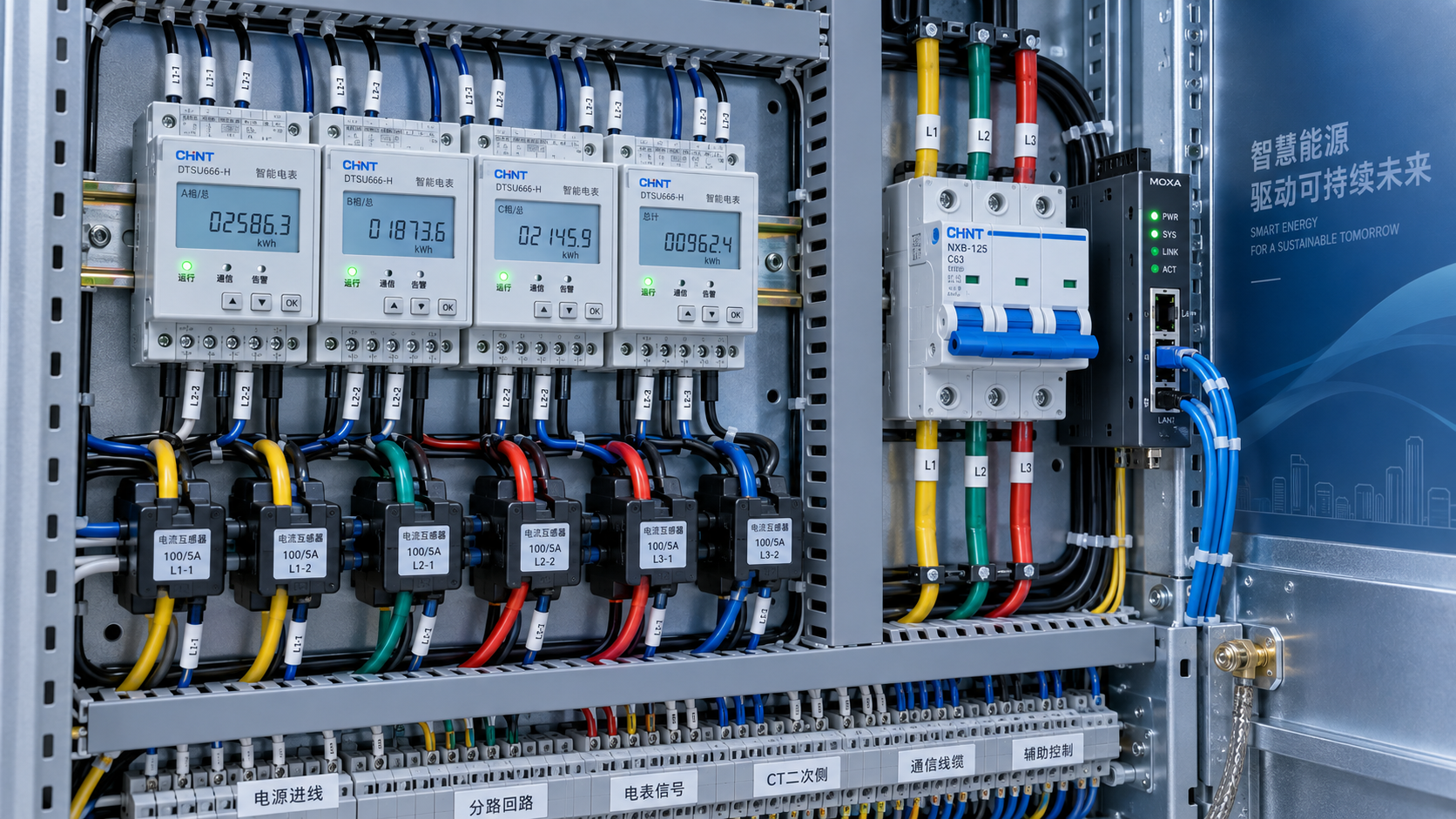
The phrase multi-circuit can be misleading. Some DIN rail smart meters accept multiple single-phase current inputs. Others are designed to calculate several three-phase loads. Some use shared voltage inputs across a panel, while others require particular voltage and current channel pairings. The product literature may describe “channels,” “circuits,” “loads,” or “CT inputs,” but those terms are not interchangeable.
A three-phase, four-wire feeder generally requires a measurement arrangement that accounts for each phase and, where relevant, the neutral and voltage configuration. A meter with twelve CT inputs does not necessarily monitor twelve independent three-phase circuits. It may monitor twelve single-phase circuits, four three-phase circuits, or a different configuration specified by the manufacturer.
Build a circuit schedule before requesting quotations. Include circuit identifier, phase arrangement, nominal voltage, expected current range, conductor size, load type, existing protection devices, and the intended reporting category. This simple document exposes issues early: circuits that cannot be accessed safely, loads supplied from different voltage systems, spare ways that may later be energized, and groups that should not be combined in one reporting total.
The circuit schedule also prevents a common mistake: buying enough CT inputs for today’s panel but no allowance for reasonable expansion. Spare channels can be useful, but a larger meter is not automatically better. Unused channels still require a clean commissioning plan so that labels, data points, and dashboard views do not become confusing.
Treat the meter and CTs as one measurement system
The meter does not determine measurement quality alone. The current transformer is equally important, and installation details can affect results more than a small difference in the meter’s stated accuracy. A technically sound selection checks the complete chain: meter accuracy, CT accuracy, CT ratio, orientation, conductor placement, voltage sensing, wiring length, and commissioning method.
First, verify the current-input type supported by the meter. Depending on the design, it may accept conventional secondary current transformers, low-voltage or millivolt-output sensors, flexible Rogowski coils, or manufacturer-specific split-core CTs. These are not freely interchangeable. A mismatch can produce invalid readings or damage equipment. Conventional CT installations also require appropriate safety procedures; their secondary circuits should never be handled casually while energized.
CT ratio selection should reflect both normal operating current and expected peaks. An oversized CT may reduce useful resolution at low loads, while an undersized CT can saturate or exceed its intended range. Facilities with highly variable loads should consider the low-load behavior that is meaningful for their analysis, not only the maximum current shown on a breaker label.
Physical fit matters as much as electrical ratio. Confirm whether the CT aperture accommodates the actual conductor, including insulation and cable routing. Split-core CTs can simplify retrofit work because conductors need not be disconnected, but their installation still depends on proper closure, correct orientation, and enough working room. Crowded switchboards often turn an apparently simple retrofit into a routing and safety exercise.
Choose accuracy and data granularity for the decision at hand
Accuracy should be discussed in context. Energy accuracy, current accuracy, and power accuracy may be specified differently, and the final system performance depends on the meter-CT combination. Ask suppliers to state which measurement condition the accuracy claim refers to, which CTs were used, and whether the stated figures apply across the intended operating range.
Beyond accumulated kWh, technical teams often need instantaneous kW, voltage, current, power factor, frequency, maximum demand, and phase-level values. The need for these points varies by application. An energy manager comparing weekly consumption may need interval data and dependable timestamps. A maintenance engineer investigating equipment behavior may need faster polling and access to electrical variables that explain why a load has changed.
Do not assume that a meter described as “smart” includes advanced power-quality functions. Harmonic measurements, event logs, waveform capture, and alarms are separate capabilities and may have distinct limits. If power-quality analysis is central to the project, verify the specific parameters, sampling behavior, event thresholds, and export method rather than relying on a broad product category.
Integration is where many otherwise sound projects lose value
A DIN rail smart meter should fit the existing or planned data architecture. In smaller installations, this may mean a local display, gateway, or simple monitoring application. Larger sites may require connection to a building management system, SCADA environment, industrial control network, cloud analytics platform, or energy-management software.
Common options include RS-485 networks using Modbus RTU, Ethernet-based communication such as Modbus TCP, and building-automation protocols such as BACnet, depending on the equipment and project design. The protocol name alone is not enough. Request the register map or point list early. Check whether the available data objects match the required metrics, whether registers are clearly documented, how device addresses are assigned, and whether cumulative energy values are exposed in usable units.
Cybersecurity and network ownership also deserve attention. A meter with an Ethernet port may need credentials, segmented network access, firmware management, or an approved gateway architecture. In some operational technology environments, a wired RS-485 field bus connected through a controlled gateway is preferred over direct IP devices. There is no universal answer; the right design follows the site’s IT and OT rules.
Data naming is less glamorous but essential. If circuit labels in the panel, meter channels, gateway points, and dashboard labels do not agree, future users will mistrust the system. Establish a naming convention and require channel-to-circuit mapping as part of commissioning documentation.
Check the panel realities before approving a model
DIN mounting creates an impression of standardization, but panel conditions vary sharply. Confirm the device width in modules or millimeters, rail availability, terminal access, cable bend radius, heat conditions, enclosure rating needs, and separation from live power wiring. The required voltage taps, protective devices, and communication terminals can consume more space than the meter body suggests.
Power supply requirements deserve the same scrutiny. Some models are powered from the monitored voltage; others require an auxiliary supply. Projects involving multiple panels, backup sources, or unusual voltage arrangements should confirm how the device behaves during outages, restarts, and loss of one phase. If timestamps, onboard logs, or configuration retention are important, those behaviors should be reviewed in the technical documentation.
Environmental conditions may also change the shortlist. Electrical rooms can expose devices to elevated temperature, dust, vibration, or electromagnetic noise. Rather than treating a general operating range as a formality, compare it with the actual cabinet conditions and the installation rules governing the site.
Evaluate suppliers through documentation and supportability
For multi-circuit monitoring, the quality of documentation is often a better early signal than a polished product image. Useful supplier material includes complete wiring diagrams, CT specifications, dimensions, supported network configurations, register maps, configuration instructions, firmware information, and a clear statement of applicable conformity documentation. Ambiguous circuit diagrams or incomplete communications manuals create commissioning risk that is difficult to price into a project.
Technical evaluators should also ask practical questions: Are replacement CTs available? Can a failed device be swapped without rebuilding the data model? Is configuration software required, and is it accessible? Does the supplier provide a consistent product lifecycle path? For cross-border procurement, verify lead times, local electrical requirements, language of manuals, warranty process, and the party responsible for technical escalation.
This is where decision-grade industry research can reduce noise. TradeNexus Pro, operating through chinaspecialmetal.com, examines technology and supply-market questions across smart electronics, green energy, advanced manufacturing, and supply-chain software. For teams comparing unfamiliar providers, structured technical information and transparent supplier context are more useful than undifferentiated listings. The goal is not to substitute a platform for engineering review, but to make the shortlist more defensible before detailed validation begins.
Commissioning should be part of the selection decision
The best selection process assumes that installation errors are possible and makes them easy to detect. Commissioning should verify CT direction, phase association, voltage reference, channel labels, communications, and plausible load values. A quick comparison with known operating conditions can reveal reversed CT polarity, swapped phases, or a circuit assigned to the wrong channel.
Plan for a small acceptance checklist before ordering. It should state which data points must appear in the target platform, the expected update frequency, the circuit naming format, and the test conditions used to confirm readings. This turns “meter installed” into a meaningful handover condition rather than the end of the contractor’s wiring work.
A suitable DIN rail smart meter is therefore not simply the one with the most features. It is the one whose circuit model, CT system, data interface, physical installation requirements, and support documentation align with the site’s actual monitoring objectives. Confirm those five areas before placing an order, and the resulting energy data is far more likely to be trusted when operational and financial decisions depend on it.
Get weekly intelligence in your inbox.
No noise. No sponsored content. Pure intelligence.
 Oct 08, 2026How Digital Health Improves Diagnostic Accuracy and Workflow in Clinical LabsHow Digital Health Improves Diagnostic Accuracy and Workflow in Clinical Labs
 Oct 07, 2026Selecting Voice Picking Systems for German Warehouses: Integration, Languages and ROISelecting Voice Picking Systems for German Warehouses: Integration, Languages and ROI
 Oct 06, 2026How to Choose Last Mile Dispatch Software for On-Time Delivery at ScaleHow to Choose Last Mile Dispatch Software for On-Time Delivery at Scale
 Oct 05, 2026Vietnam’s Consumer Electronics Market: Demand Shifts and Sourcing OpportunitiesVietnam’s Consumer Electronics Market: Demand Shifts and Sourcing Opportunities
 Oct 04, 2026Digital Health Investment Priorities for Providers: Improving Access, Outcomes, and EfficiencyDigital Health Investment Priorities for Providers: Improving Access, Outcomes, and Efficiency
 Oct 03, 2026How to Specify an FR4 Custom PCB Board for High-Voltage and High-Heat DesignsHow to Specify an FR4 Custom PCB Board for High-Voltage and High-Heat Designs
 Oct 02, 2026ERP Software Market Intelligence: Adoption, Pricing, and Vendor Signals to WatchERP Software Market Intelligence: Adoption, Pricing, and Vendor Signals to Watch
 Oct 01, 2026How to Select Calibrated Temperature Data Loggers for GMP Cold Storage MonitoringHow to Select Calibrated Temperature Data Loggers for GMP Cold Storage Monitoring
 Sep 30, 2026Custom Molded Rubber Pricing: What Drives Unit Cost and Tooling Fees?Custom Molded Rubber Pricing: What Drives Unit Cost and Tooling Fees?
 Sep 29, 2026How to Evaluate Energy Management Software Vendors for Multi-Site OperationsHow to Evaluate Energy Management Software Vendors for Multi-Site Operations
 Sep 28, 2026How to Select a DIN Rail Smart Meter for Multi-Circuit Energy MonitoringHow to Select a DIN Rail Smart Meter for Multi-Circuit Energy Monitoring
 Sep 27, 2026TWS Earbuds in Vietnam: Demand Drivers, Price Tiers, and Retail Channel OpportunitiesTWS Earbuds in Vietnam: Demand Drivers, Price Tiers, and Retail Channel Opportunities
 Sep 26, 2026How UAE Clinics Can Qualify a Smart Glucometer Supplier for Accuracy and ComplianceHow UAE Clinics Can Qualify a Smart Glucometer Supplier for Accuracy and Compliance
 Sep 25, 2026Buying Aesthetic Lasers in the USA: FDA Status, Wavelengths, and Service SupportBuying Aesthetic Lasers in the USA: FDA Status, Wavelengths, and Service Support
 Sep 24, 2026Laser Cutting Brass Sheet: How to Prevent Burrs and Heat Marks on Thin PartsLaser Cutting Brass Sheet: How to Prevent Burrs and Heat Marks on Thin Parts
 Sep 23, 2026How to Choose Lightweight ANC Headphones for Comfortable All-Day TravelHow to Choose Lightweight ANC Headphones for Comfortable All-Day Travel
 Sep 22, 2026IPX5 TWS Bluetooth Earbuds: What Protection Do They Offer for Workouts?IPX5 TWS Bluetooth Earbuds: What Protection Do They Offer for Workouts?
 Sep 21, 2026What to Look for in a Grid Integration Company for Utility-Scale Solar ProjectsWhat to Look for in a Grid Integration Company for Utility-Scale Solar Projects
 Sep 20, 2026Microgrid Controller Pricing: What Drives Cost in Commercial Energy Projects?Microgrid Controller Pricing: What Drives Cost in Commercial Energy Projects?
 Sep 19, 2026How to Choose a GaN Charger for Laptops Without Compromising Power or PortabilityHow to Choose a GaN Charger for Laptops Without Compromising Power or Portability
 Sep 18, 2026Floating Solar Farm Costs: CAPEX, OPEX, and the Site Factors That Shape ROIFloating Solar Farm Costs: CAPEX, OPEX, and the Site Factors That Shape ROI
 Sep 17, 2026Drone Delivery Solutions for Last-Mile Routes: Site, Payload, and Range PlanningDrone Delivery Solutions for Last-Mile Routes: Site, Payload, and Range Planning
 Sep 16, 2026When Low-Volume Electronics Manufacturing Makes More Sense Than Mass ProductionWhen Low-Volume Electronics Manufacturing Makes More Sense Than Mass Production
 Sep 15, 2026Wholesale WiFi Smart Switches: What Buyers Should Verify Before OrderingWholesale WiFi Smart Switches: What Buyers Should Verify Before Ordering
 Sep 14, 2026How to Select IoT Sensors for Reliable Monitoring in Harsh Industrial EnvironmentsHow to Select IoT Sensors for Reliable Monitoring in Harsh Industrial Environments
 Sep 13, 2026How Procurement Teams Can Improve Supplier Reliability With Supply Chain VisibilityHow Procurement Teams Can Improve Supplier Reliability With Supply Chain Visibility
 Sep 12, 2026Smart Manufacturing Trends 2026: What Leaders Should Prioritize for ROISmart Manufacturing Trends 2026: What Leaders Should Prioritize for ROI