Choosing Between Six-Sided Drilling and CNC Routing for Cabinets
A cabinet shop choosing between a six-sided drilling machine and a CNC router is often deciding where hole-making should sit in the production flow. If panels are already cut and edgebanded, a dedicated drilling machine may complete face and edge holes with limited handling. If the same machine must cut parts from sheets, rout openings and produce varied shapes, a CNC router may cover more operations, although some edge work may require another setup or machine.
The decision turns on the actual mix of holes, panel sizes and upstream operations. Six-sided capability is not interchangeable across machines: spindle arrangement, clamping, supported panel dimensions and software all determine which features can be completed in one pass. A useful comparison begins with representative cabinet parts rather than headline machine speeds.
How the two approaches produce cabinet holes
A six-sided drilling machine is generally designed to process panels that have already been cut to size. Depending on its configuration, drilling units can work on the two broad faces and the four edges while the panel is positioned and held by clamps or another transport system. The term “six-sided” describes the intended access to the panel, not a guarantee that every hole direction, diameter or position is possible without repositioning.
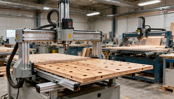
A CNC router typically holds a sheet or panel on a table and moves a spindle to cut features from above. A router can drill with suitable tooling and, when equipped with a dedicated drill bank, may execute groups of vertical holes using independently selected spindles. Routing also supports profiles, pockets, grooves and cutouts. Horizontal drilling depends on the machine’s equipment and access to the relevant edges; it should not be assumed from the presence of a CNC control alone.
For evaluators considering these distinctions, the drilling machine and CNC router comparison provides related context on how the two machine categories approach cabinet-panel processing. The practical issue is not which name sounds more versatile, but whether the proposed configuration can produce the required features without unacceptable manual work.
Map the holes before comparing cycle times
Start with a sample of production orders that reflects ordinary work as well as awkward exceptions. Include side panels with shelf-pin rows, hinge locations, connector holes and any edge drilling; add tops, bottoms, shelves, drawer components and finished ends if they are part of the intended workload. For each part, record material, thickness, finished dimensions, hole diameter and depth, entry face, edge reference and any visible surface.
The direction of a hole matters as much as its count. A panel with many vertical shelf holes may suit either a router with an appropriate drill bank or a dedicated drilling machine. A panel that also needs horizontal connector holes introduces a different question: can the router reach those edges while the part is securely held, or must an operator move it to a separate machine? Conversely, a component with extensive pockets and a shaped perimeter may make better use of a router even if a downstream drilling pass remains necessary.
Check minimum and maximum panel dimensions against the supplier’s actual processing envelope, including thickness and weight. A machine may accept a panel physically but restrict drilling near a clamp, prevent a particular combination of features, or require a special handling method. Narrow rails and small drawer parts deserve separate attention because clamping and vacuum retention can become more difficult as usable holding area decreases.
Compare the complete route through the shop
Machine cycle time alone can favor the wrong option. A nested router may cut several parts from a sheet and drill accessible face holes in the same setup. The remaining workflow can still include unloading, sorting, edgebanding and edge drilling. A six-sided machine may process both face and edge holes after edgebanding, but it relies on upstream cutting and usually does not replace the equipment used to create the panel shapes.
Draw the route for each representative part from raw sheet to assembly-ready component. Include program preparation, material loading, labeling, sorting, setup, machining, transfer, inspection and rework. Identify operations that can run in parallel as well as those that block the next step. For example, adding a drilling machine may reduce manual repositioning at the drilling stage while creating a queue if cut panels cannot be delivered consistently or operators are shared with edgebanding.
Batch size also changes the calculation. Repeated parts may benefit from a stable setup and predictable handling. High-mix orders place more weight on reliable part identification, automatic program selection and the ability to change between panel sizes without extra fixtures. A fast machining cycle is less valuable if labels are incorrect or an operator must repeatedly verify which face is up.
Use a common production sample
Ask each supplier to evaluate the same part drawings, material specifications and expected order mix. Define where the timed process starts and ends: a quoted drilling cycle may exclude loading, barcode scanning, clamp repositioning or unloading. Where a machine cannot perform an operation, add the time and handling required at the alternative workstation rather than treating the operation as free.
Separate estimated performance from a witnessed demonstration. A demonstration on one favorable panel can establish that a feature is possible, but it does not establish production capacity across a changing mix. Ask for the assumptions behind any simulation, including tool changes, panel spacing, drilling sequences and operator actions.
Examine drilling quality at the feature level
A hole can be present and still cause assembly problems. Position errors between mating panels can prevent connectors from engaging; a depth error can leave insufficient material behind a blind hole or allow a fastener to bottom out. Chipped laminate around a visible face hole may be unacceptable even when the hardware fits. Define acceptance criteria for each feature in the purchase documents, using the cabinet hardware requirements and the shop’s assembly needs.
Evaluate position from the same datum used in the drawing. On a panel with edge drilling, measure the relationship between edge holes and face holes, not just each group independently. Variation can come from panel sizing, incorrect squareness, positioning against a stop, movement under cutting force or program reference errors. The drilling machine cannot compensate for an out-of-square panel unless the process and software are set up to account for it.
Inspect hole diameter, depth, surface breakout and the condition of the opposite face where relevant. Test the actual board construction and decorative surface: particleboard, MDF and laminated panels can respond differently to tool geometry and wear. A clean result in a demonstration is meaningful only when tooling, feed conditions and material are comparable with production.
For routers, confirm how the panel or nested parts are held while drilling and cutting. A small part can shift as surrounding material is removed, changing subsequent hole positions. For clamp-fed drilling equipment, check whether clamping leaves marks on finished surfaces and whether the machine must release and regrip a panel to reach certain positions. Both situations should be tested rather than resolved by a general claim of accuracy.
Software and data flow can determine usable capacity
The machine must receive the right program for the right physical panel. Verify how cabinet design data becomes machine instructions, which software handles drilling patterns and whether the proposed postprocessor supports the installed drill heads, aggregate tools and workholding arrangement. A program that runs on one configuration may need modification for another.
Trace a part through labeling and orientation. If a drilling machine reads a barcode, establish what happens when a label is missing, damaged or applied to the wrong face. If an operator selects a program manually, assess how similar left- and right-hand panels are distinguished. Mirrored parts are a useful test because an incorrect reference face can place an otherwise accurate pattern on the wrong side.
Clarify how revisions are controlled when hardware changes. The buyer should know who updates the tool library, verifies drilling depths and approves the new program before production. Include recurring software costs, backup procedures, user access and the availability of postprocessor support in the evaluation; these are operating dependencies, not just commissioning details.
Account for ownership, maintenance and integration
Compare investment against the work each machine actually removes from the route. A router may consolidate sheet cutting, profiling and some drilling, but it can require vacuum equipment, spoilboard maintenance, dust extraction and tooling for several operations. A dedicated drilling machine may need its own infeed and outfeed arrangements and still depend on a panel saw or router upstream. The relevant cost is the combined cost of the required process, not the purchase price of a single machine.
Request a breakdown of installation requirements, consumables, tooling, preventive maintenance, replacement parts and training. Check available floor space around loading and unloading zones, not just the machine footprint. Consider how panels move between cutting, edgebanding and drilling, and whether a failure at the new machine would stop the line or whether an alternate process exists.
Safety provisions should be assessed for the installed configuration and operating jurisdiction. Review guarding and interlocks, dust extraction, emergency-stop arrangements, access for tool changes and the supplier’s instructions alongside the site’s own risk assessment. OSHA’s woodworking machinery guidance identifies hazards associated with moving cutters and material handling; its Woodworking eTool is a useful reference for US workplaces, while applicable requirements elsewhere must be checked locally.
Write acceptance tests around difficult parts
Before purchase, agree on a test set that includes the largest and smallest intended panels, a narrow component, a mirrored pair and a panel with holes on several faces. Include at least one part with a feature near a likely clamping area and, for a router, a small nested part that must remain fixed through its final operation. The selection should reflect the buyer’s drawings rather than generic supplier samples.
Specify the board and surface, tooling, reference edges, hole locations, permissible deviations and inspection method. Record which operations are included, whether panels are turned or regripped, and what manual intervention is necessary. Verify that each finished part fits its intended hardware or mating component where a functional check is appropriate. Any excluded feature should be assigned to a named downstream process.
Record results for a sequence of parts, not only the first acceptable example. A sequence helps reveal whether handling, tool wear, labeling or changing panel dimensions affects the process. It is not a substitute for a formal capability study where one is required, but it gives both parties a clearer basis for resolving discrepancies before handover.
A six-sided drilling machine is a strong candidate when accurately prepared rectangular panels need substantial face and edge hole work after cutting or edgebanding. A router is often the more flexible starting point when sheet nesting, profiles and cutouts dominate, provided its drilling configuration and downstream operations cover the required holes. The final choice should rest on a documented route, representative part tests and the cost of completing every feature—not on the number of sides named in a specification.
Source for workplace safety context: Occupational Safety and Health Administration, Woodworking eTool, “Machine Hazards” and related woodworking safety guidance.
Get weekly intelligence in your inbox.
No noise. No sponsored content. Pure intelligence.
 Nov 22, 2026Golmud's 60 MW Liquid Air Storage Project Uses Fully Domestic EquipmentGolmud's 60 MW Liquid Air Storage Project Uses Fully Domestic Equipment
 Nov 22, 2026Precision Engineering for Medical Devices: Tolerances and MaterialsPrecision Engineering for Medical Devices: Tolerances and Materials
 Nov 21, 2026EDF Acquires 1GWh Holloway Battery Storage Project in AustraliaEDF Acquires 1GWh Holloway Battery Storage Project in Australia
 Nov 21, 2026Choosing Carbon Steel Grades for OEM Machined Parts: Key FactorsChoosing Carbon Steel Grades for OEM Machined Parts: Key Factors
 Nov 20, 2026China’s First Virtual Power Plant Report Says Capacity Target Met EarlyChina’s First Virtual Power Plant Report Says Capacity Target Met Early
 Nov 20, 2026Choosing an OEM Heavy Equipment Manufacturer: Capabilities and Quality ChecksChoosing an OEM Heavy Equipment Manufacturer: Capabilities and Quality Checks
 Nov 19, 2026India Adds Record 8.4 GW of Open-Access Solar in First Nine Months of 2026India Adds Record 8.4 GW of Open-Access Solar in First Nine Months of 2026
 Nov 19, 2026B2B Intelligence for Green Energy: Finding New Market OpportunitiesB2B Intelligence for Green Energy: Finding New Market Opportunities
 Nov 18, 2026Global Solar Additions Hit Record in 2025, Forecast to Fall in 2026Global Solar Additions Hit Record in 2025, Forecast to Fall in 2026
 Nov 18, 2026Supply Chain Visibility for Supplier Management: How to Spot Delivery RisksSupply Chain Visibility for Supplier Management: How to Spot Delivery Risks
 Nov 17, 2026US Battery Storage Deployment Tops 200 GWh; 74 GWh Forecast for 2026US Battery Storage Deployment Tops 200 GWh; 74 GWh Forecast for 2026
 Nov 17, 2026Choosing a Solar Tracker for Ground-Mount PV: Site and Design FactorsChoosing a Solar Tracker for Ground-Mount PV: Site and Design Factors
 Nov 16, 2026US Polysilicon and Solar Product Tariffs and Import Price Floor Take Effect December 4US Polysilicon and Solar Product Tariffs and Import Price Floor Take Effect December 4
 Nov 16, 2026How Industrial Buyers Can Evaluate B2B Intelligence Reports on SuppliersHow Industrial Buyers Can Evaluate B2B Intelligence Reports on Suppliers
 Nov 15, 2026CATL Sets Tener Sodium Delivery Timeline, Targeting LFP on CostCATL Sets Tener Sodium Delivery Timeline, Targeting LFP on Cost
 Nov 15, 2026Electric Wheelchairs for Disabled Adults: Choosing the Right Fit and RangeElectric Wheelchairs for Disabled Adults: Choosing the Right Fit and Range
 Nov 14, 2026China Expects Clean Energy to Meet All New Electricity Demand by 2030China Expects Clean Energy to Meet All New Electricity Demand by 2030
 Nov 14, 2026Choosing a Digital X-Ray Detector Supplier: Compatibility and SupportChoosing a Digital X-Ray Detector Supplier: Compatibility and Support
 Nov 13, 2026Ecuador Sets Zero VAT and Currency Outflow Tax Rates for Solar and Storage EquipmentEcuador Sets Zero VAT and Currency Outflow Tax Rates for Solar and Storage Equipment
 Nov 13, 2026Choosing an OEM Machined Parts Manufacturer: Quality, Capacity and Lead TimesChoosing an OEM Machined Parts Manufacturer: Quality, Capacity and Lead Times
 Nov 12, 2026South Africa Registers 2 GW of New Solar PV Capacity in Q3 2026South Africa Registers 2 GW of New Solar PV Capacity in Q3 2026
 Nov 12, 2026Mexico Supply Chain Market Research: Nearshoring Opportunities and RisksMexico Supply Chain Market Research: Nearshoring Opportunities and Risks
 Nov 11, 2026US Senate Advances Bipartisan BAAJA Energy Permitting BillUS Senate Advances Bipartisan BAAJA Energy Permitting Bill
 Nov 11, 2026Inventory Management Decision Support: When and How Much to ReorderInventory Management Decision Support: When and How Much to Reorder
 Nov 10, 2026China's Trade Surplus Tops $1 Trillion Through October as Exports Rise 35.2%China's Trade Surplus Tops $1 Trillion Through October as Exports Rise 35.2%
 Nov 10, 2026Choosing Surgical PPE: Gowns, Gloves, Masks and Eye ProtectionChoosing Surgical PPE: Gowns, Gloves, Masks and Eye Protection
 Nov 09, 2026US Solar Imports Shift as Domestic Manufacturing Investment Reshapes Global TradeUS Solar Imports Shift as Domestic Manufacturing Investment Reshapes Global Trade