Choosing a Low-Speed Centrifuge: RCF, Capacity, and Rotor Compatibility
Choosing among low speed centrifuge machines requires more than comparing maximum RPM or advertised capacity. A suitable system must produce the required relative centrifugal force (RCF) with the actual rotor and vessels used, while processing the required number of samples within the available time.
The most important specification is therefore not a centrifuge’s highest individual rating, but the performance of a complete configuration: instrument, rotor, buckets, adapters, vessels and operating settings. A machine can meet a stated speed requirement yet fall short of the required force, or advertise sufficient capacity while accommodating fewer of the intended tubes than expected.
Start with the required force, not the highest RPM
RCF describes the acceleration applied to a sample relative to gravity and is expressed as a multiple of g, such as 2,000 × g. RPM describes rotational speed. The two are related, but RPM alone does not determine the force experienced by a sample: the distance from the rotor axis also matters.
For a specified radius, the relationship is:
RCF = 1.118 × 10⁻⁵ × radius in cm × RPM2
For example, at 3,000 RPM, a radius of 10 cm produces approximately 1,006 × g, while a radius of 15 cm produces approximately 1,509 × g. The same speed setting therefore does not necessarily reproduce the same separation conditions on a different rotor.
The radius used for a calculation must also be identified. Manufacturers may report maximum RCF at the bottom of a vessel, where the radius is greatest, while a protocol or instrument setting may refer to another position. The force varies along the sample column, so two quoted RCF values are not directly comparable unless their reference positions are understood.
If a method specifies RCF, confirm that the proposed rotor can achieve it with the selected vessel and adapter without exceeding any component’s speed limit. If the method specifies RPM only, obtain the original rotor and radius information before translating the setting to another instrument. An RPM value without that context is not a reliable transfer specification.
RCF is not the whole method, however. Separation also depends on run time, sample properties, geometry, temperature and acceleration and braking behavior. Reaching the same maximum RCF is a useful starting point for comparison, not proof that two configurations will produce equivalent results.
Check the rotor-specific operating envelope
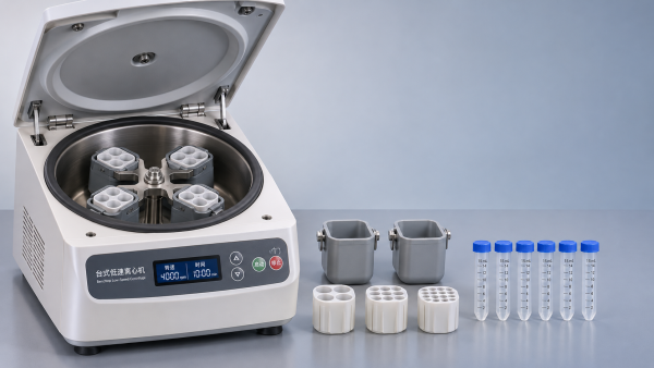
A centrifuge’s headline maximum speed or maximum RCF may apply only to a particular rotor. A high-capacity rotor can have a lower permitted speed than a smaller rotor, and a vessel or adapter can impose a lower limit than the rotor itself. Evaluation should use the most restrictive approved limit for the complete assembly.
Request the manufacturer’s specifications for the exact combination being considered, including:
- The rotor’s maximum permitted RPM and the corresponding RCF, with the radius or reference position stated.
- Approved buckets, carriers, adapters and vessels, including any lower component-specific limits.
- Permitted maximum load and fill conditions for the configuration.
- Any restrictions on temperature, run duration or use of particular accessories.
Be careful when a catalog lists “maximum capacity” and “maximum RCF” in the same summary. Those figures may come from different rotors. Unless the supplier confirms otherwise, they should not be treated as simultaneous capabilities.
Some instruments allow entry of a target RCF and calculate the corresponding RPM from a selected rotor. That feature is useful only if the correct rotor is selected and the instrument’s RCF reference matches the method’s requirements. Where radius values can be entered manually, the value should be controlled as part of the operating method rather than left to operator assumption.
Capacity means usable samples per cycle
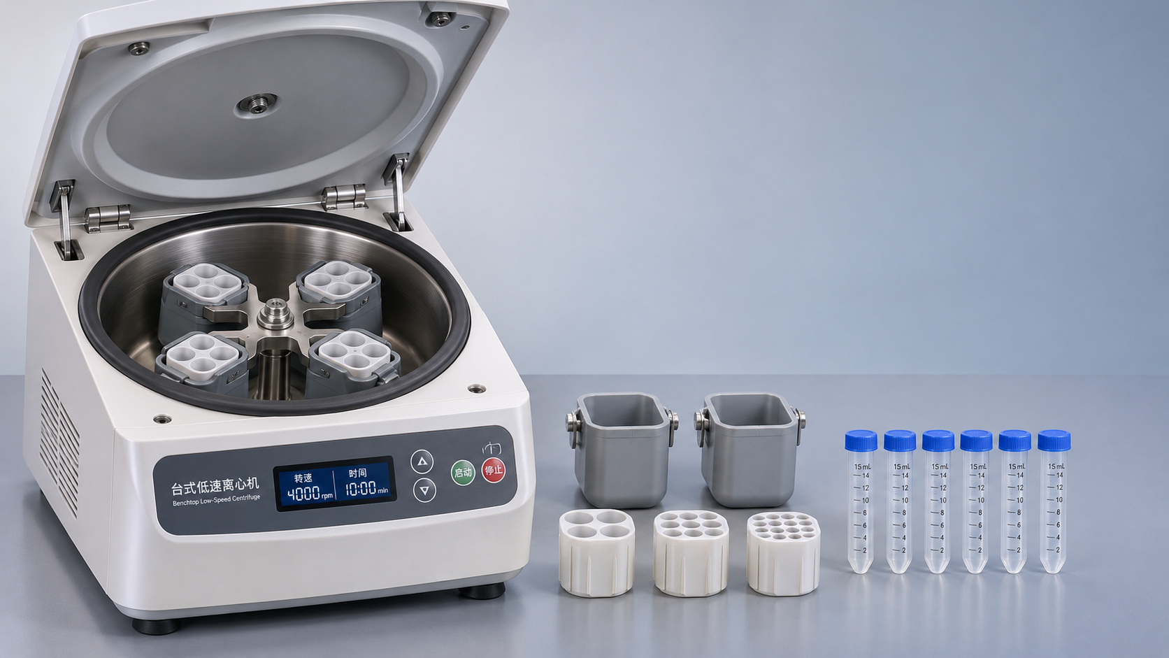
Capacity is often expressed as the number of positions multiplied by nominal vessel volume, such as 4 × 250 mL. This describes a possible loading arrangement, not necessarily the number of the tubes used in a particular process. A bucket designed for a large bottle may require an insert to hold smaller tubes, and that insert determines how many tubes fit.
Tube dimensions are as important as nominal volume. Two tubes with the same stated volume can differ in length, diameter, base shape and cap design. A vessel may physically enter an adapter yet lack proper support, clearance or manufacturer approval for centrifugation. Confirm the exact vessel identification or its dimensional and material specification against the accessory documentation.
Usable capacity should be calculated from the actual loading arrangement:
Usable samples per run = approved vessel positions in the selected rotor configuration − positions unavailable because of loading or balancing constraints.
Not every run will require empty positions, but odd sample counts or particular rotor layouts may require a balance vessel instead of an additional sample. Balancing is based on the manufacturer’s instructions and, where required, the mass of the loaded opposing assemblies—not simply on filling tubes to visually similar levels.
Run time alone also understates the time between batches. Loading, balancing, acceleration, deceleration, unloading and any cleaning or temperature preparation all affect the cycle. For an illustrative schedule, a 20-minute separation within a 30-minute total cycle permits two completed cycles per hour only if loading and turnaround can actually be maintained at that pace. With 16 usable samples per cycle, that is an illustrative upper rate of 32 samples per hour; interruptions or incomplete loads reduce it.
Compare that rate with the arrival pattern of samples, not just an average daily volume. A centrifuge that can process the daily total may still be unsuitable if most samples arrive together and must be processed within a limited window.
Rotor geometry changes how a method behaves
Low-speed instruments commonly offer fixed-angle or swinging-bucket rotors, but their differences are not limited to capacity. In a fixed-angle rotor, vessels remain inclined during rotation. In a swinging-bucket rotor, buckets move outward as speed increases, placing vessels closer to horizontal during the run.
That geometry affects the direction and distance over which material sediments, where a pellet forms and how readily a separated layer can be removed. A fixed-angle configuration can be suitable where compact pelleting and shorter sedimentation paths are important. A swinging-bucket configuration can be useful when distinct layers and access to a horizontal interface matter. Neither geometry is automatically equivalent to the other at the same stated RCF and time.
Vessel geometry adds another variable. Changing from a narrow tube to a wider bottle, for example, changes the sample column and sedimentation path. Even if the total volume and maximum RCF match, the resulting separation may differ. If an existing procedure depends on a particular interface, pellet location or recovery step, the proposed rotor and vessel should be assessed against those practical requirements.
Where a validated method specifies a rotor type, vessel or braking profile, a substitution should follow the applicable change-control and validation process. Manufacturer compatibility confirms that an assembly may be operated within its limits; it does not establish that a modified method delivers an equivalent result.
Compatibility extends beyond physical fit
A usable assembly has a chain of approved parts: centrifuge, rotor, bucket or carrier where applicable, adapter, vessel and closure. Compatibility at one connection does not establish compatibility across the rest of the chain. A third-party tube that appears to fit an insert may not have been evaluated for that rotor’s loading conditions, cap clearance or centrifugal force.
For each intended vessel, establish the approved fill range, closure requirements and any material restrictions. Vessel ratings can depend on factors such as temperature, chemical exposure and the support provided by the adapter. A vessel’s standalone RCF rating should not be assumed to authorize every rotor-and-adapter combination.
Sample containment also deserves configuration-specific review. A sealed tube cap, a sealed bucket and an aerosol-tight rotor lid are different components with different intended functions. If containment is required, confirm the manufacturer’s stated performance and instructions for the complete assembly, including seals and closures. Select handling and opening procedures under the applicable laboratory risk assessment; a sealed accessory does not eliminate the need for appropriate controls.
Finally, check inspection and replacement requirements. Rotor service life, corrosion, cleaning agents, damaged adapters and seal condition can affect whether a configuration remains suitable over time. Availability of replacement buckets, inserts and seals is relevant because a centrifuge is only as usable as its supported accessories.
Operating conditions can decide between otherwise similar machines
Temperature control: If samples are temperature-sensitive, determine whether refrigeration is required and what temperature must be maintained at the sample. A chamber setpoint alone does not prove sample temperature throughout acceleration, the run and unloading. Load size, starting temperature, rotor and ambient conditions can affect the result, so the proposed configuration may need verification under representative conditions.
Acceleration and braking: Fast braking can shorten turnaround but may disturb a loose pellet or separated layers. Confirm whether acceleration and deceleration profiles are adjustable and whether the selected program can reproduce the conditions required by the method. If a no-brake or slow-brake setting is needed, include the resulting deceleration time in the throughput calculation.
Run control: Check when the timer starts: at the start of rotation, after reaching the set speed, or according to another selectable convention. The distinction matters when transferring a short protocol. Also establish whether the instrument records actual speed, elapsed time and alarms if those records are needed for the workflow.
Installation: Confirm footprint, clearance, electrical supply, ventilation and the mass of the instrument with its intended rotor. Lid opening clearance and access for lifting a loaded rotor or bucket can affect placement even when the machine fits on the bench.
Compare complete configurations before approval
A consistent evaluation uses the same workload and method requirements for each candidate. Rather than requesting a generic brochure, specify the sample vessels, required force, run time, number of samples per batch, temperature needs and any containment requirements. Ask the supplier to identify the exact rotor and accessories needed to meet them.
A compact comparison can expose gaps that headline specifications conceal:
Where performance is critical, a representative trial should use the intended vessels, fill volumes, rotor, settings and sample or an appropriate surrogate. Acceptance criteria should be defined before the trial—for example, the required separation or recovery result and the allowable processing time. This distinguishes a configuration that meets a catalog specification from one that can support the intended method in routine operation.
Get weekly intelligence in your inbox.
No noise. No sponsored content. Pure intelligence.
 Nov 07, 2026MIIT Seeks Feedback on One-Code-Per-Robot Identification ProposalMIIT Seeks Feedback on One-Code-Per-Robot Identification Proposal
 Nov 07, 2026Choosing a Low-Speed Centrifuge: RCF, Capacity, and Rotor CompatibilityChoosing a Low-Speed Centrifuge: RCF, Capacity, and Rotor Compatibility
 Nov 06, 2026China's New Energy Storage Capacity Reaches 167 GWChina's New Energy Storage Capacity Reaches 167 GW
 Nov 06, 2026Geothermal Heat Pumps for Schools: Site and Retrofit ConsiderationsGeothermal Heat Pumps for Schools: Site and Retrofit Considerations
 Nov 05, 2026Australian Grid-Forming Battery Trial Completed as Akaysha Seeks ContractsAustralian Grid-Forming Battery Trial Completed as Akaysha Seeks Contracts
 Nov 05, 2026Smart Kitchen Appliances for Meal Prep: Which Ones Save the Most Time?Smart Kitchen Appliances for Meal Prep: Which Ones Save the Most Time?
 Nov 04, 2026Solar Inverter Makers Raise Prices, Fueling Margin Recovery ExpectationsSolar Inverter Makers Raise Prices, Fueling Margin Recovery Expectations
 Nov 04, 2026Choosing Ophthalmic Equipment for Hospitals: Key Clinical and Purchasing CriteriaChoosing Ophthalmic Equipment for Hospitals: Key Clinical and Purchasing Criteria
 Nov 03, 2026Amazon Raises European FBA Fuel and Logistics Surcharge to 2% From November 2Amazon Raises European FBA Fuel and Logistics Surcharge to 2% From November 2
 Nov 03, 2026How Exporters Can Build an Editorial Framework for Overseas MarketsHow Exporters Can Build an Editorial Framework for Overseas Markets
 Nov 02, 2026China-Peru Free Trade Agreement Upgrade Takes Effect November 1China-Peru Free Trade Agreement Upgrade Takes Effect November 1
 Nov 02, 2026Choosing Digital Blood Pressure Monitors for Accurate Home ReadingsChoosing Digital Blood Pressure Monitors for Accurate Home Readings
 Nov 01, 2026Laboratory Equipment Prices: Budgeting for Purchase and Operating CostsLaboratory Equipment Prices: Budgeting for Purchase and Operating Costs
 Oct 31, 2026Chinese Portable Energy Storage Firms Report Overseas Order Growth in Q3Chinese Portable Energy Storage Firms Report Overseas Order Growth in Q3
 Oct 31, 2026SCARA Robot Cycle Times: How Payload and Travel Distance Affect SpeedSCARA Robot Cycle Times: How Payload and Travel Distance Affect Speed
 Oct 30, 2026Walmart and Symbotic Sign $6 Billion Global Automation AgreementWalmart and Symbotic Sign $6 Billion Global Automation Agreement
 Oct 30, 2026Choosing a Waterproof Folding Solar Charger: IP Ratings and Power OutputChoosing a Waterproof Folding Solar Charger: IP Ratings and Power Output
 Oct 29, 2026Poland to End SENT Registration for Certain Scrap Metal Road Shipments on October 28Poland to End SENT Registration for Certain Scrap Metal Road Shipments on October 28
 Oct 29, 2026Energy Storage System Quotation: How to Compare Scope and Hidden CostsEnergy Storage System Quotation: How to Compare Scope and Hidden Costs
 Oct 28, 2026BNEF Raises US Battery Storage Forecast 30%, Sees 213.9 GW by 2030BNEF Raises US Battery Storage Forecast 30%, Sees 213.9 GW by 2030
 Oct 28, 2026Global Trade Intelligence Pricing: Data Coverage, User Seats, and API CostsGlobal Trade Intelligence Pricing: Data Coverage, User Seats, and API Costs
 Oct 27, 2026Western Australia 1GW Data Centre With 5GWh Battery Enters Federal Review ProcessWestern Australia 1GW Data Centre With 5GWh Battery Enters Federal Review Process
 Oct 27, 2026USB-C Docking Stations in the UK: A Buyer's Guide to Compatibility and ChargingUSB-C Docking Stations in the UK: A Buyer's Guide to Compatibility and Charging
 Oct 26, 2026AgiBot Scales Up Production as 100 Expedition A3 Robots Stage Guinness Record AttemptAgiBot Scales Up Production as 100 Expedition A3 Robots Stage Guinness Record Attempt
 Oct 26, 2026Rehabilitation Equipment for Outpatient Clinics: What to Check Before BuyingRehabilitation Equipment for Outpatient Clinics: What to Check Before Buying
 Oct 25, 2026Teradyne Robotics and Sereact Partner on AI-Powered Returns AutomationTeradyne Robotics and Sereact Partner on AI-Powered Returns Automation
 Oct 25, 2026Smart Warehousing Integration: How to Connect Robots to an Existing WMSSmart Warehousing Integration: How to Connect Robots to an Existing WMS